Introduzione

You can use this guide to learn the steps to remove the touchpad of your Dell XPS 15 9570. The keypad allows for user input and interaction with the device. A faulty keypad makes operating the device difficult to impossible.

Prior to starting this guide, be sure the laptop is powered off and it is unplugged from the charging cord.

  1. XDM21s2U3cke3sGH
    • Make sure your device is powered off and unplugged before starting

    • Flip the device over so the base cover of the computer is facing upwards.

  2. d1TkpNtEmj1gYkSq
    d1TkpNtEmj1gYkSq
    JvcaxuB3RfDfEGdd
    XwugwAd2HEwvmXtf
    • Using a Torx T5 screwdriver, remove the ten 3 mm screws on the back.

  3. YrsOILKZD1PRTYwJ
    YrsOILKZD1PRTYwJ
    Fe25FODYZtLlMT2f
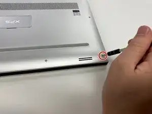
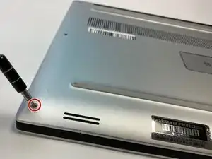
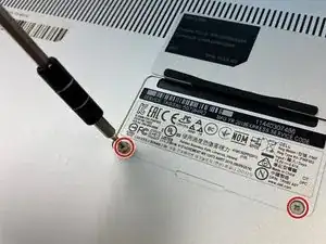
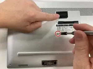
    • Flip open the system badge and with a Phillips #00 screwdriver, remove the two 8.5 mm screws.

  4. KVZHHmymMGCjCZTD
    • Lift the back cover off of the device.

  5. JUxdS4psiWRxTvZG
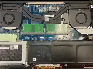
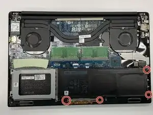
    • Using the Phillips #00 screwdriver, remove the four 4 mm screws holding the battery in place.

    For laptops with the larger battery, there are actually 9 screws to remove.

    nebman227 -

    My previous comment is incorrect, it is 7 screws, not 9, for the larger battery

    nebman227 -

    in the red circles wrong screws marked.

    Eugenio Rodriguez -

  6. LQBoPGVRdlPDyOw2
    • Use the iFixit opening tool to disconnect the battery connector from the motherboard.

  7. dDCbvb1B1h5jM2LC
    • With your hands, pick up and remove the battery from the system.

    Just right except my battery was full width.

    William Corwin -

  8. CBE11KkBaDB1W14u
    CBE11KkBaDB1W14u
    WH1oQGErV4YBE1M2
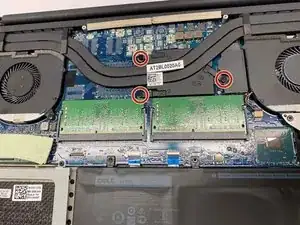
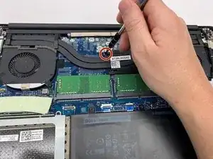
    • Use the Phillips #00 to remove the three (without graphics card) or four (with graphics card) 3 mm screws that connect the heat sink to the system board.

  9. HdqVHZpTaA6WM6xH
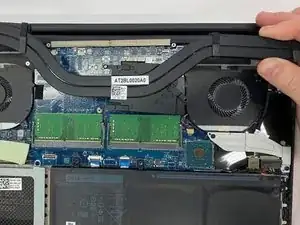
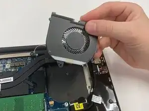
    • Lift the heat sink from the device. The thermal paste may have dried and make this handling more complicated, be careful.

  10. Vvk6mrinQbB3UfCJ
    Vvk6mrinQbB3UfCJ
    UXVlmY2DoiFBivpo
    • Use the Phillips #00 screwdriver to remove the two 4 mm screws securing the grey display cable bracket.

  11. DCyLCHWJjPdAD1Yl
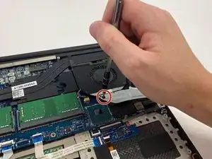
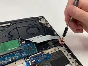
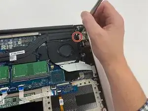
    • Using the Phillips #00 screwdriver, remove the 4 mm screw at the back right corner of the fan.

  12. pfcSR6kDt3OxNycN
    pfcSR6kDt3OxNycN
    ZjIeLVyKsmMSdUxs
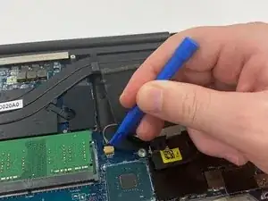
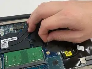
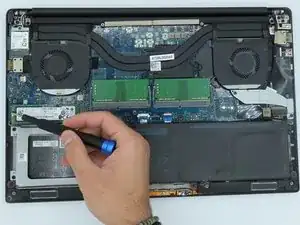
    • Disconnect the fan cable on the left of the fan and on the right side from the RAM, using the opening tool.

  13. GxGJSs4vOUq2daOX
    • Lift the right fan off of the device.

    • Repeat steps 8-11 to remove the left fan from the system board.

    • The left fan is fixed with two 4 mm screws. Make sure you have removed them if the fan does not come off easily.

  14. LGxeILqR22ISukKV
    LGxeILqR22ISukKV
    K15IknmN4VLqYyPB
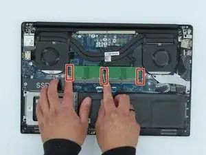
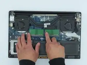
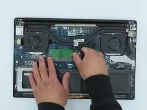
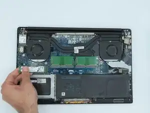
    • Use your fingers to pinch down the metal tabs holding the RAM in place. Do this for each tab.

  15. F1Mem5kYfOgAoAI3
    • Use your hands to carefully lift the RAM up and away from the tabs to safely take it out.

  16. 32234IPMkgI1QKIp
    32234IPMkgI1QKIp
    W2ZdAsF5RXMLDPM1
    • Use the Phillips #00 screwdriver to remove the 5.5 mm screw next to the SSD.

  17. LV5LmxISZrkrDU2K
    LV5LmxISZrkrDU2K
    DCqnYgQUTcKnlSUA
    • Using your hands, hold the SSD and slightly pull to the left.

  18. MGkiNhGZ4fmajPQR
    MGkiNhGZ4fmajPQR
    MsTp2dHnHhRuFFQh
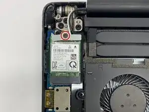
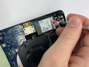
    • Using a Phillips #00 screwdriver, loosen the captive screw holding the wireless card bracket in place.

  19. ksiINHTL5ejZLA1d
    • Lift the wireless card bracket off of the wireless card.

  20. OuBr3yxMkWnmI4iN
    OuBr3yxMkWnmI4iN
    3MZCS1vCk2DEPahO
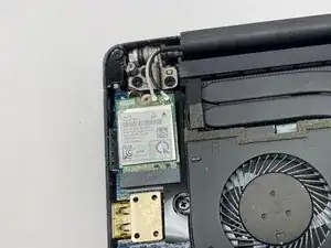
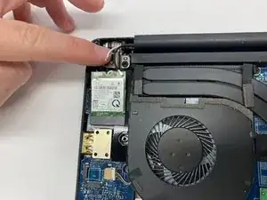
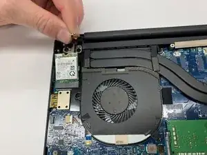
    • Using a spudger, disconnect the coaxial antenna cables from the Wi-Fi card by popping them gently off.

  21. OSsqj4Qd2JJX1pZD
    • Carefully remove the wireless card.

  22. EP3Cui5M1IEBu1Vb
    EP3Cui5M1IEBu1Vb
    G6dSpInOnBp3g1rg
    • Using the iFixit opening tool, disconnect the speaker cable by pulling it out gently.

  23. iJv61nsngyVPXXUq
    iJv61nsngyVPXXUq
    nvxR3662eF5OTBFG
    PPIIYwR31QojFL1B
    • Remove the four 2mm screws using the Phillips #00 screwdriver.

    • There are two on the left speaker and two on the right.

    • Follow the images for the right side to complete the left side as well.

  24. XWDqyRCHtHMHqAng
    • Remove the speakers from the back of the computer.

  25. On1bhQNRkPa1bcNb
    On1bhQNRkPa1bcNb
    4wPkPGrVRuiqLgjE
    • Disconnect the two motherboard cables using the opening tool.

  26. VnhHPjTvIX6WQjRd
    VnhHPjTvIX6WQjRd
    pwuH4214CwbSCR2x
    ymWOfhFI2Nrm1uxs
    • Using a Phillips #0 screwdriver, remove the four 4mm screws securing the hard drive cover.

  27. t2FUSLHyXpwb4QJa
    t2FUSLHyXpwb4QJa
    2YNV3IihitPwSFfX
    TkJmwgs1YJ26br56
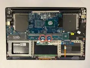
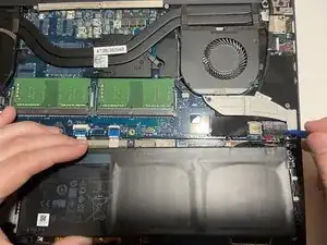
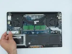
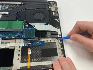
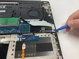
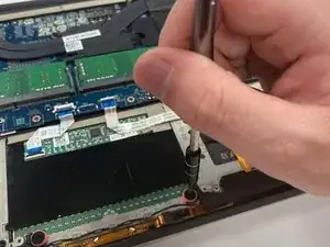
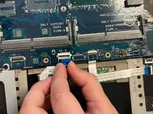
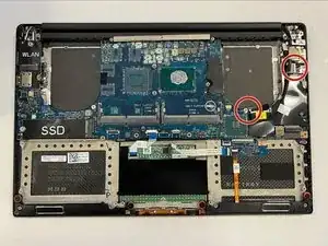
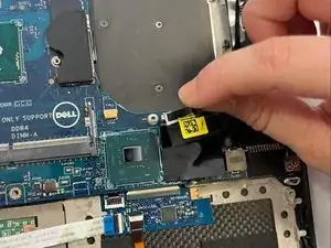
    • Disconnect the two motherboard cables located on the right of the motherboard using the opening tool.

  28. ZqB112rs5b42HynB
    ZqB112rs5b42HynB
    AaMIpSvtMWnfJTF3
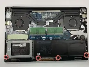
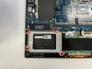
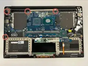
    • Using a Phillips #0 screwdriver, unscrew the 4 remaining 4mm screws holding the motherboard in place.

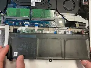
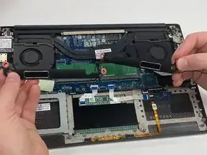
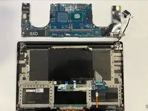
    • Remove the motherboard.

  29. 16fFTfvn42yxWFFX
    16fFTfvn42yxWFFX
    V6POBDQ5ZjsETZfQ
    VnlePcSsUJEVhZrg
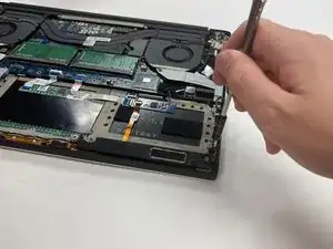
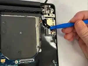
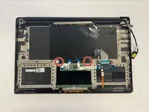
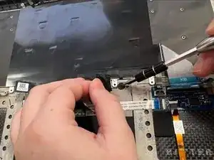
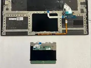
    • Using a Phillips #0 screwdriver, unscrew the two 2.4mm screws holding the touchpad in place.

    • Remove the touchpad.

Conclusione

To reassemble your device, follow these instructions in reverse order.

Sophie

Membro da: 09/11/23

289 Reputazione

0 commenti