Introduzione

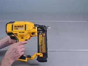
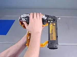
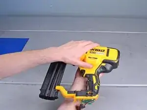
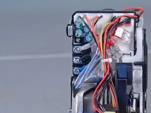
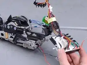
This guide shows how to remove and replace the control module for the Dewalt Nailers DCN680D1 2018.

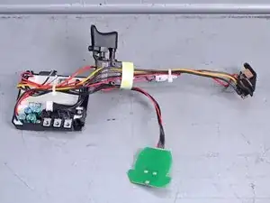
The module is an all-in-one assembly, which includes the trigger mechanism, battery connector, and selector switch board.

  1. cVQdYFAkWBwF1jkU
    cVQdYFAkWBwF1jkU
    6QneiNayynNDJI4h
    6mAcC4BRgVw5VWPW
    • Before you begin the repair, remove the battery from the device.

  2. avdWFSfwXMkBUWeR
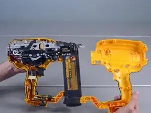
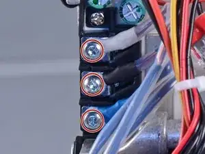
    • Remove the following screws securing the outer housing:

    • Twelve T10 screws

    • One 2.5 mm hex screw

    • Some of these screws are deeply recessed. You can use a flathead screwdriver to loosen these screws.

  3. kTyfgndnlOmVvetD
    kTyfgndnlOmVvetD
    CTZmEOn3CS2OeI3t
    • Lift and remove the right housing from the device.

  4. hOY6uevTVcJKlAob
    hOY6uevTVcJKlAob
    6eTkNQ4XmsNtOMK2
    • Remove the lock button from its recess.

    • During reassembly, make sure that the button is properly seated and engages the trigger.

  5. ESYp4VAAuJgV1LHD
    ESYp4VAAuJgV1LHD
    OQVoYJhVhJVkM2Yw
    • Slide the battery connector out of its recess.

  6. WKrEZMGNQHOyUjJ4
    WKrEZMGNQHOyUjJ4
    Kb6RS5EoxPTEtmRE
    bJRDYFmglPjgGWKh
    • Remove the switch board, switch, and spring from its housing recess.

    • During reassembly, use the third photo as a reference to help you set the components back in the housing.

  7. KAlCeRpEYNCR1Egm
    KAlCeRpEYNCR1Egm
    LPvpMKZhrjYcSIl3
    P5JaZeT1FgOjwYfi
    • Carefully flip the device over.

    • Remove the left housing from the device.

  8. yXxjQXoERVDTGelV
    yXxjQXoERVDTGelV
    WQuIrHQcX61fRyYy
    MWrauaHmQF3ig2GX
    • The spring under the release button has a tendency to fly out. Be careful not to lose the spring.

    • Carefully remove the release button from the device.

    • Remove the button spring from the device.

    Interesting, my stall release lever button has a totally different internal shape/latch. The entire thing was jammed...

    SCShopgirl -

  9. QQRZlUcBNVPNOXHZ
    QQRZlUcBNVPNOXHZ
    b2o3AKPHQvxcmKT5
    • Use a T20 driver to remove the two screws (one on either side) securing the back support .

  10. OODmLoR4lp4ItUhR
    OODmLoR4lp4ItUhR
    XQtDJLx2WqxTReZd
    • Loosen the two solenoid wires from the back support.

  11. 6EEo6W2QPGIdiplO
    6EEo6W2QPGIdiplO
    QGmdkoPaIE1UUIdo
    • Pull the back support straight out of the device.

  12. 3ABLrFLVTEyJi5HN
    3ABLrFLVTEyJi5HN
    HwIUSiyYLxgStYB3
    • Use a T10 driver to remove the three screws securing the motor wires

    • Reassembly tip: The motor wires are color-coded. Be sure to reconnect the motor wires as shown in the photo.

  13. SMFeTZ5NCsaQdHkV
    SMFeTZ5NCsaQdHkV
    6E2RKepSXAL5bDla
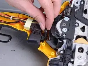
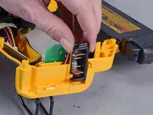
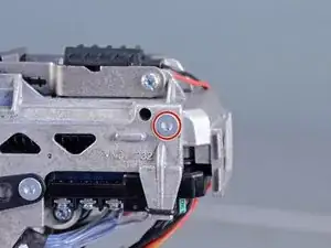
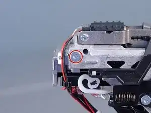
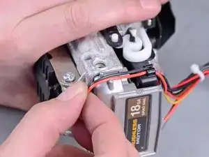
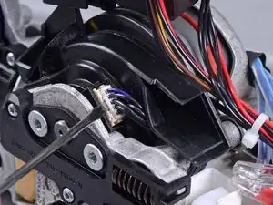
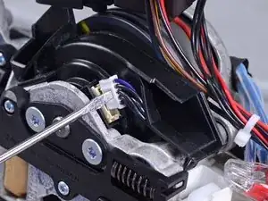
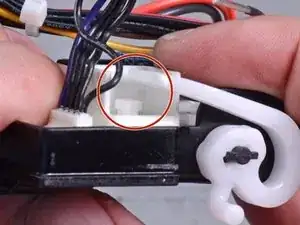
    • Use a small flathead screwdriver to pry up and disconnect the sensor connector from the side of the motor.

  14. Q2QPrXZahM2Ebqdv
    Q2QPrXZahM2Ebqdv
    XUkDlVqd1ZlBZIOF
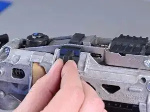
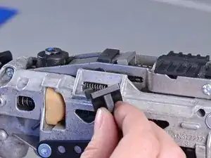
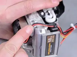
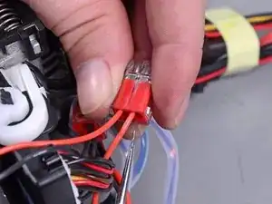
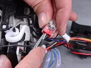
    • Insert the point of a pick tool into the push-in connector's inlet hole, which has the control module wire plugged into it.

    • Make sure you choose the inlet that connects to the control module, not the solenoid.

  15. VCZ44XUrFxHt3PPg
    VCZ44XUrFxHt3PPg
    rgyHeBvGubSFtTDu
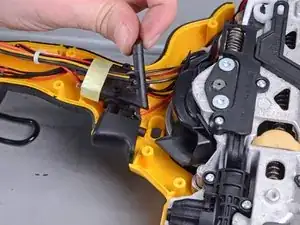
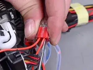
    • With the pick tool still inserted, pull the red control module wire out of the push-in connector.

  16. U1FNu1qNTZQgJydP
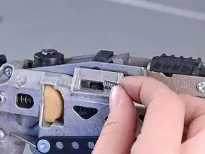
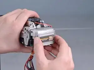
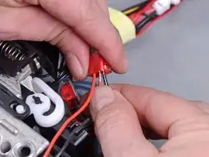
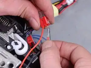
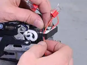
    • Repeat the previous two steps to disconnect the black control module wire from the push-in connector.

  17. 1IPFTGbFu6XDiMmV
    1IPFTGbFu6XDiMmV
    PlHM3obIP2ZqkwwS
    • Unclip the solenoid's red and black wires from the control module's side.

  18. TwOYA5L5XAZWaeNE
    TwOYA5L5XAZWaeNE
    bkYkSN4twqQOieof
    oRgvUSihQZGviLQr
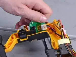
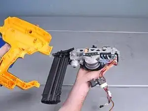
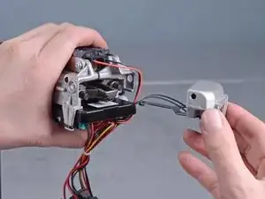
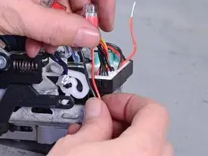
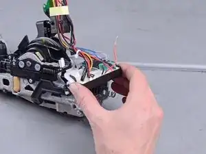
    • Lift and remove the control module from the device.

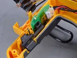
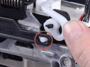
    • Reassembly tip: Make sure that the white plastic actuator latches into the black lever arm.

  19. vPRTGDkEBaa123O2
    vPRTGDkEBaa123O2
    O2REDkTFIHjsnONC
    KwTR2GO3BrEfQOTC
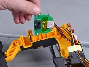
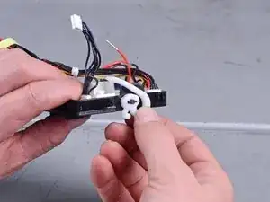
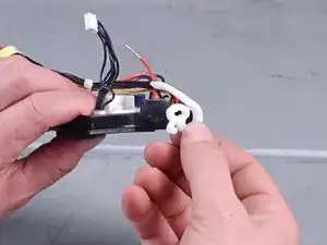
    • Remove the white plastic actuator from the control module and transfer it onto your replacement part.

    • When you install the actuator, make sure the actuator bar can press the white button on the control module.

  20. b4hPEN3sVJWSBFe1
    • Only the control module remains.

Conclusione

To reassemble your device, follow these instructions in reverse order.

Arthur Shi

Membro da: 03/01/18

248257 Reputazione

0 commenti