Introduzione

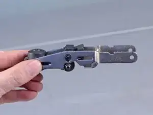
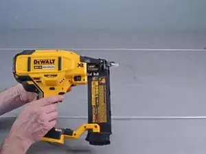
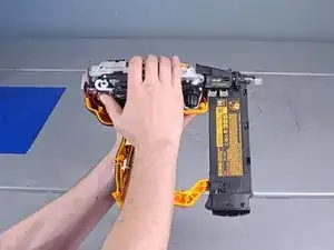
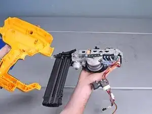
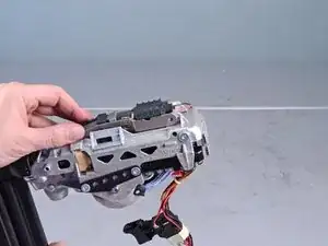
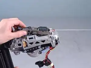
This guide shows how to remove and replace the PTO assembly for the Dewalt Nailers DCN680D1. The replacement part does not come with some minor components, so you must transfer them from the original part.

  1. cVQdYFAkWBwF1jkU
    cVQdYFAkWBwF1jkU
    6QneiNayynNDJI4h
    6mAcC4BRgVw5VWPW
    • Before you begin the repair, remove the battery from the device.

  2. avdWFSfwXMkBUWeR
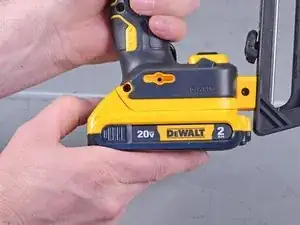
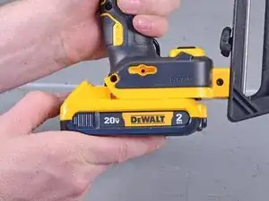
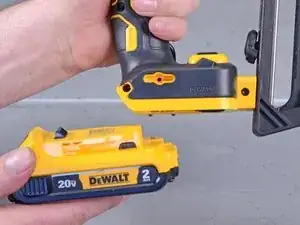
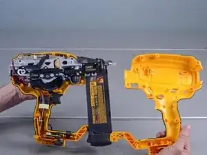
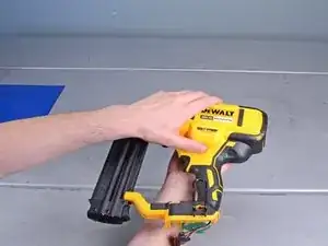
    • Remove the following screws securing the outer housing:
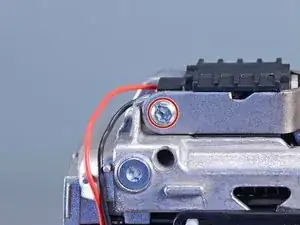
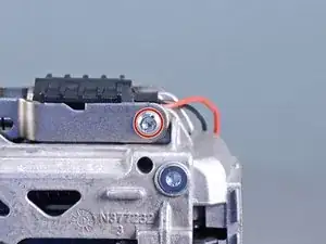
    • Twelve T10 screws

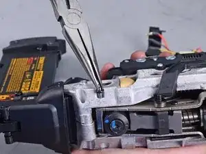
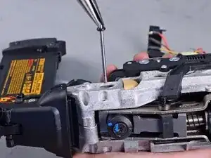
    • One 2.5 mm hex screw

    • Some of these screws are deeply recessed. You can use a flathead screwdriver to loosen these screws.

  3. kTyfgndnlOmVvetD
    kTyfgndnlOmVvetD
    CTZmEOn3CS2OeI3t
    • Lift and remove the right housing from the device.

  4. hOY6uevTVcJKlAob
    hOY6uevTVcJKlAob
    6eTkNQ4XmsNtOMK2
    • Remove the lock button from its recess.

    • During reassembly, make sure that the button is properly seated and engages the trigger.

  5. ESYp4VAAuJgV1LHD
    ESYp4VAAuJgV1LHD
    OQVoYJhVhJVkM2Yw
    • Slide the battery connector out of its recess.

  6. WKrEZMGNQHOyUjJ4
    WKrEZMGNQHOyUjJ4
    Kb6RS5EoxPTEtmRE
    bJRDYFmglPjgGWKh
    • Remove the switch board, switch, and spring from its housing recess.

    • During reassembly, use the third photo as a reference to help you set the components back in the housing.

  7. KAlCeRpEYNCR1Egm
    KAlCeRpEYNCR1Egm
    LPvpMKZhrjYcSIl3
    P5JaZeT1FgOjwYfi
    • Carefully flip the device over.

    • Remove the left housing from the device.

  8. yXxjQXoERVDTGelV
    yXxjQXoERVDTGelV
    WQuIrHQcX61fRyYy
    MWrauaHmQF3ig2GX
    • The spring under the release button has a tendency to fly out. Be careful not to lose the spring.

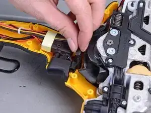
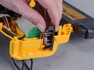
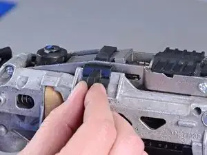
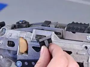
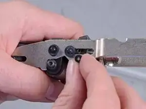
    • Carefully remove the release button from the device.

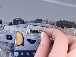
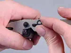
    • Remove the button spring from the device.

    Interesting, my stall release lever button has a totally different internal shape/latch. The entire thing was jammed...

    SCShopgirl -

  9. QQRZlUcBNVPNOXHZ
    QQRZlUcBNVPNOXHZ
    b2o3AKPHQvxcmKT5
    • Use a T20 driver to remove the two screws (one on either side) securing the back support .

  10. OODmLoR4lp4ItUhR
    OODmLoR4lp4ItUhR
    XQtDJLx2WqxTReZd
    • Loosen the two solenoid wires from the back support.

  11. 6EEo6W2QPGIdiplO
    6EEo6W2QPGIdiplO
    QGmdkoPaIE1UUIdo
    • Pull the back support straight out of the device.

  12. alW21K6rCXaZgpvH
    alW21K6rCXaZgpvH
    SnJGFeIs6UkuoAw5
    • Slide the dowel pin securing the PTO assembly out of the device.

  13. 4COuFhZHar2K1CHl
    4COuFhZHar2K1CHl
    lSGBrqbvHPhPbPWK
    • Use a T10 driver to remove the two screws securing the solenoid.

  14. nkYMuM45QlMjQn4L
    nkYMuM45QlMjQn4L
    UwYgJEfTKYwaGEQL
    l1EdtmMHXPPUGdQB
    • Lift the solenoid away from the device.

    • The solenoid is still connected to the device by two wires. Be careful not to strain the wires.

  15. wOTT5Eiso5egj2tF
    wOTT5Eiso5egj2tF
    2xAYlIeysweOSUw6
    C2CfBVZdb3AG1ZhO
    • Slide the solenoid off the PTO assembly's rails.

  16. Ag63n1nmF64CLIyn
    Ag63n1nmF64CLIyn
    IoLtA6KhBhUR133Y
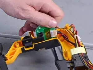
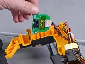
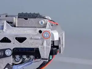
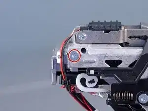
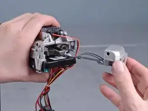
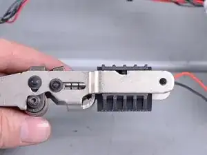
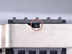
    • Reassembly tip: When you slide the solenoid back onto the PTO assembly, make sure to align the plastic pin to the notch.

  17. TClUM2T1nRyROaUs
    TClUM2T1nRyROaUs
    NGkVJLvXwDAnALXp
    kqKqbYMIZdIRxTry
    • Use a flathead screwdriver to pry off the rubber stopper securing the plunger pin.

    • Retain the rubber stopper and washer for your replacement assembly.

  18. eGbexUS2nyKW2qAd
    eGbexUS2nyKW2qAd
    pdV4B4HBNxRdw3cw
    • Remove the plunger pin from the PTO assembly.

  19. SNJFy2t3rkkuHhwW
    SNJFy2t3rkkuHhwW
    sNrITEAAqLfHsMxL
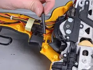
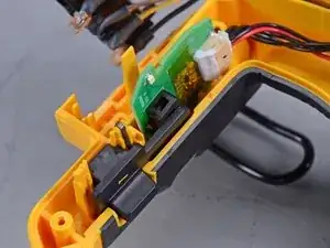
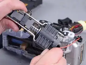
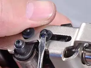
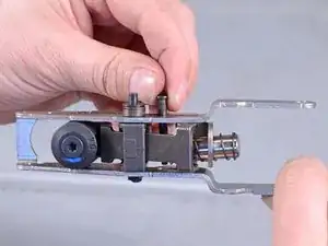
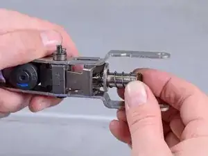
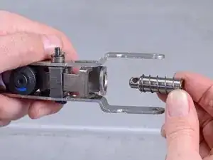
    • Remove the plunger and spring from the PTO assembly.

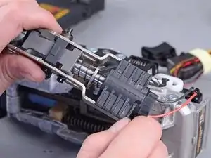
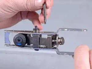
    • Install the plunger, spring, and pin onto your replacement assembly.

  20. BXR5FyTCx1syjPZP
    • Only the PTO assembly remains.

Conclusione

To reassemble your device, follow these instructions in reverse order.

Arthur Shi

Membro da: 03/01/18

248257 Reputazione

0 commenti