Introduzione

This guide will show you how to remove the main camera lens assembly from the camera's frame.

  1. ZgmSVK6peCUBf5g4
    ZgmSVK6peCUBf5g4
    5DZJGlOkKtKhZxmg
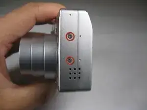
    • Remove the following screws:

    • Two silver 3.15mm Phillips #00 screws on the right side of the camera

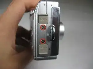
    • Two silver 2.08mm Phillips #00 screws on the left side of the camera

  2. Ti2MvaIh4iSGDH3s
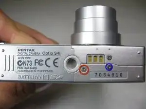
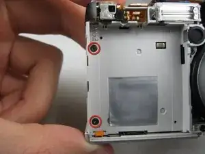
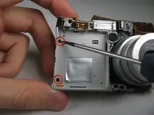
    • Remove the two indicated screws on the bottom of the camera:

    • The screw circled in red is a longer silver 3.15mm Phillips #00 screw

    • The screw circled in blue is a shorter silver 2.25mm Phillips #00 screw

  3. rKw34AmCEhmfFhgE
    rKw34AmCEhmfFhgE
    vDRrY3eqsohAgLjH
    • Carefully pull the back of casing away from the front.

  4. TGBSGe6PpZ11OVdL
    TGBSGe6PpZ11OVdL
    iOSWVovFCHRbIs6T
    ElILR2jSQVCxaeAx
    • After removing the back cover, several things must be removed.

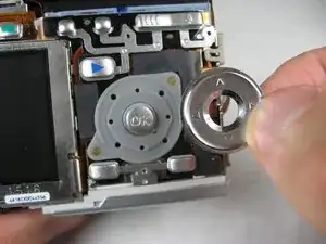
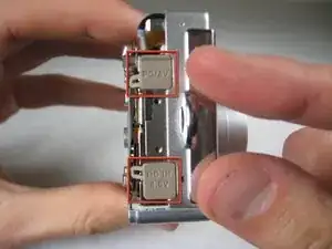
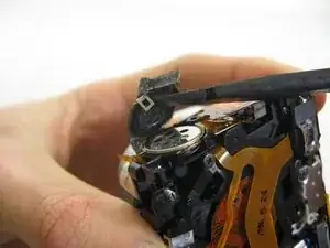
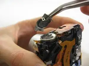
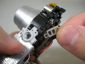
    • Silver donut-shaped button will fall off. Place separately. Remove the plug covers on the right side of camera, labeled “PC/AV” and “DC IN 4.5V”.

  5. MTriUeWyE6Up5xBj
    MTriUeWyE6Up5xBj
    2p3RoehZlahhOBFn
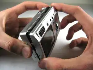
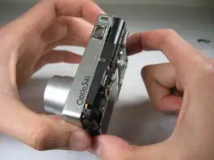
    • To remove the front cover, gently hold the inside structure of the camera and slowly pull the front cover off.

  6. RMroNjINRHArGyeI
    RMroNjINRHArGyeI
    lCdpX3WQGPxFAEiJ
    • On the front of the camera, in battery case, remove screws indicated:

    • Two black 2.05mm Phillips #00 screws

  7. WQOeJNaSbTwNcsDt
    WQOeJNaSbTwNcsDt
    Z1FQl4QA22ms32GZ
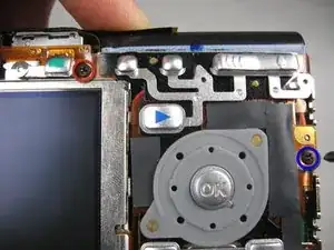
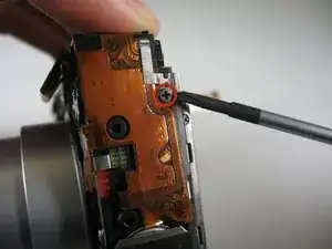
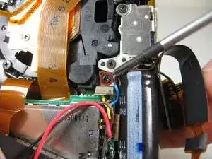
    • Flip the camera over to the backside and remove screws indicated:

    • The screw circled in red is a longer black 3.00mm Phillips #00 screw

    • The screw circled in red is a shorter black 2.00mm Phillips #00 screw

  8. GTiZx4gKo4myjeHB
    • Pull the cover plate off for the two power cord jacks.

  9. HAxEQrFYaMGQBRgZ
    HAxEQrFYaMGQBRgZ
    AkIg3EuaNwvynN2A
    Gnrp1kFTbYihsVdX
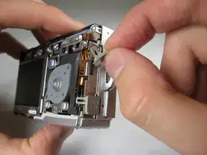
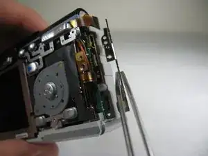
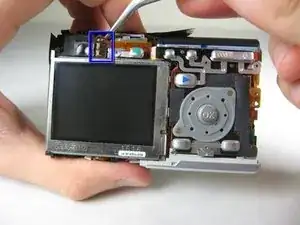
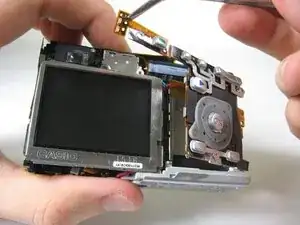
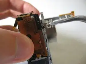
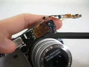
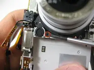
    • Cautiously and gently pull up the control board at the upper left corner, next to the viewfinder.

  10. SnV11aW5w55FiEDJ
    • Remove the orange tape on top of the SD cardholder.

  11. tQYoYYUP4SG1CUKS
    tQYoYYUP4SG1CUKS
    jAB3654L3YTkCplk
    Z3HZJOOJGNHXv33T
    • Open the battery cover and lift plastic piece off.

  12. k3ajIojyJmwvCQnG
    • Remove tape on left side of camera.

  13. lBS6iYeZ53dFK2Xv
    • Remove the indicated 2.40mm Phillips #00 screw to release top left LCD bracket.

  14. yr2FBrqVHNNyKbWG
    • Remove top left LCD bracket.

    • This is a small piece, be careful not to lose it.

  15. LuetwHUBYIKr4Oqf
    LuetwHUBYIKr4Oqf
    WdOP6FFQFrQJQIZE
    • Push down bottom left LCD bracket to release the LCD from grip.

  16. CTPiM2EAWwxYPAeR
    • Gently lift up LCD screen.

  17. CGfHtjEslnWBWHZg
    CGfHtjEslnWBWHZg
    LxVYlZGjVA3UehOI
    OZlHXXg4kcSbIiwy
    • Slowly pull LCD screen to the left to remove it from the other grips.

    • BEWARE: The LCD screen is attached to the logic board by two wires at the bottom.

  18. BvsuOTtJkmkB4dTQ
    BvsuOTtJkmkB4dTQ
    tTadJxOEbGoIIbXI
    b4OJb3INdGvVGPAo
    • Lift up tape slightly on both sides of speaker.

  19. uTq1OT5C5PlCNOHD
    uTq1OT5C5PlCNOHD
    uFYYUSCQJKjAjOZX
    6Y2fCvrV5e1QM2HQ
    • Use the pointed end of a spudger to lift up brackets.

    • Lift speaker cover out.

  20. NDSsbeOWXNndckCZ
    • Remove speaker cover.

  21. YkHdX1GaC3crlKki
    YkHdX1GaC3crlKki
    EMQvWN6UJdtBU4qY
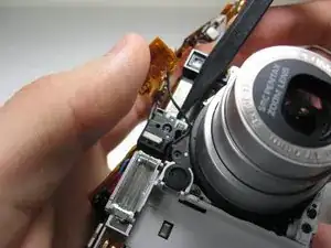
    • Turn camera to front.

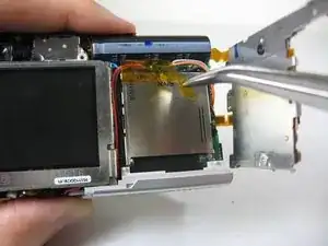
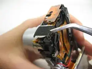
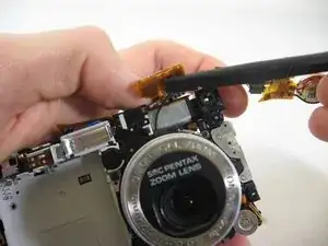
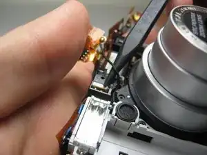
    • Carefully peel off orange wire tape. The tape is glued to the surface indicated.

    • Lift speaker from holder.

  22. DFjacgPsIpcKEKRT
    DFjacgPsIpcKEKRT
    ANx1MR2Albte1F6J
    • Use a wedge to lift up the wire tape flap.

  23. xa5xXn2cXkbaOc1O
    xa5xXn2cXkbaOc1O
    anLLMLLsIqqCjo3X
    t2fOBPvQqLSulk44
    • Insert the point of a spudger underneath the wire shown.

  24. GCqlbaPcHEsrwkpP
    GCqlbaPcHEsrwkpP
    DUrA1VqdYDCysGPP
    • Carefully lift the wire out of the crevasses.

  25. lgY2fk4xKbSVmxHI
    • Slowly bend the speaker's wire tape away from the lens assembly. Avoid creasing the tape.

  26. dXiu2ttphkWFHfoU
    dXiu2ttphkWFHfoU
    SlumYEHNlCRoeExk
    TMfEArc2EWTjQ2uM
    • Remove indicated screws:

    • Three Black 3.80mm Phillips #00 screws.

  27. hbd5TOwiB5Q2VclT
    hbd5TOwiB5Q2VclT
    PjRt4hEQSofAYTbw
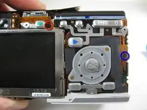
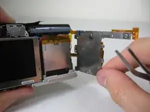
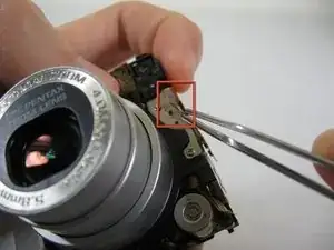
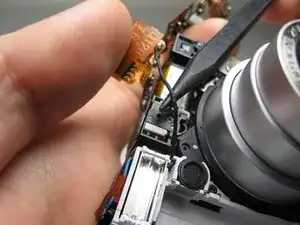
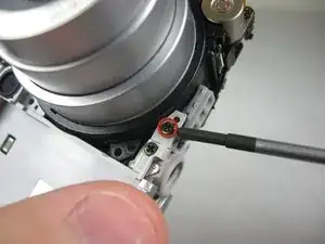
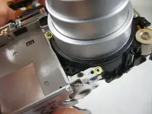
    • Remove the indicated black 3.40mm Phillips #00 screw on the bottom of the camera.

    • Remove copper leads.

  28. 6uQJUZBuvXV4BCIJ
    6uQJUZBuvXV4BCIJ
    aPcUmypAUkrg2ajZ
    xbZKeM15ULUcII6n
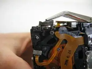
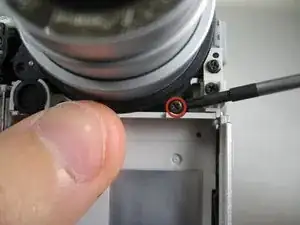
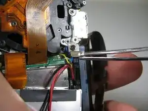
    • Unscrew the indicated 3.80mm Phillips #00 screw on the back of the camera.

    • Remove screw and bracket.

  29. 31OQLEIPITAWcnlX
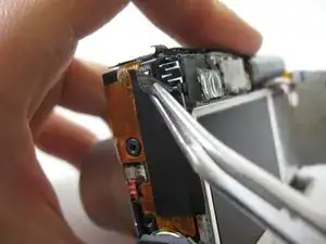
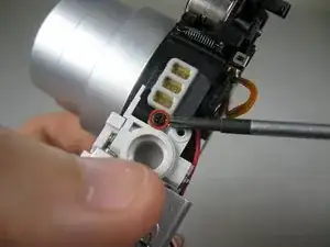
    • Turn the camera over to the front.

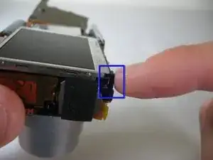
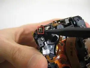
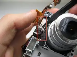
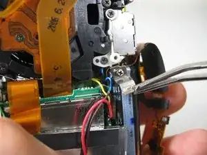
    • In the following step, you will undo the indicated pegs. PROCEED TO THE NEXT STEP.

  30. kFOdsu3enqTvW3Nw
    kFOdsu3enqTvW3Nw
    MboIf6TNDcQ6AZQY
    2bnoBbxuGWnPEmHT
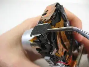
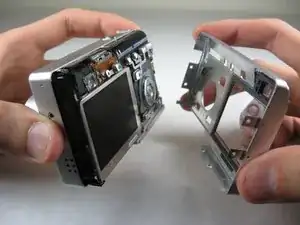
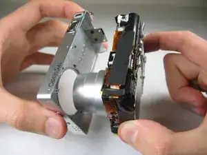
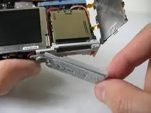
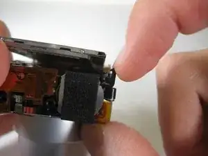
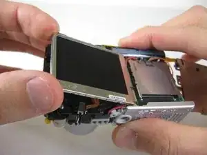
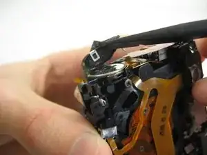
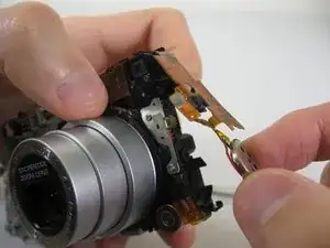
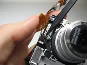
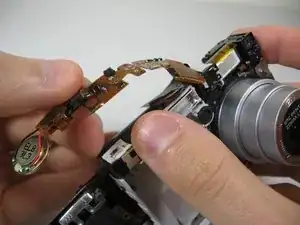
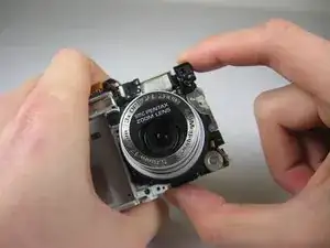
    • Carefully holding the camera, grab the corresponding two points.

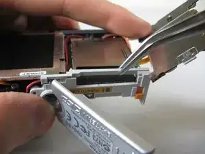
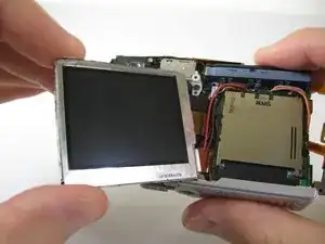
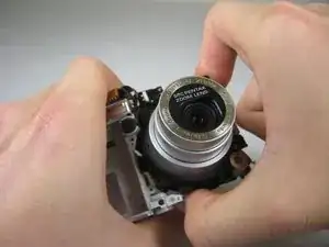
    • Carefully twist the lens assembly away from you. You will be turning your hand clockwise.

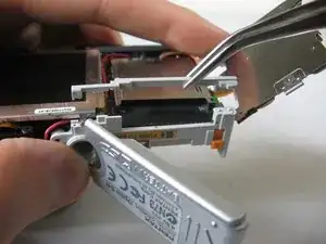
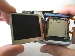
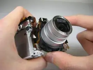
    • Pull lens assembly out.

    • The lens assembly is attached to the logic board by wire tape.

Conclusione

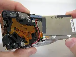
To reassemble your device, follow these instructions in reverse order.

Bassem Tossoun

Membro da: 21/01/11

201 Reputazione

2 commenti

Do you have this disassembly steps for the S12?

ThoH -

Lens will Not focuscorrectly

ThoH -