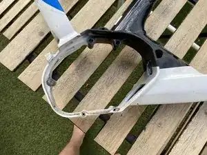
Introduzione

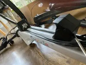
I wanted to paint my bike’s frame in a paint shop, so I dissasembled everything from the frame.

I had two identical bikes, and learned a lot along the way. I documented everything along the way, and applied some optimizations to the process afterwards, thus the images often contain parts, that are not there by the time (since this last order of actions is the best). Hope you still find it helpful!

  1. fXTb6DLH6GKrEmk5
    fXTb6DLH6GKrEmk5
    1iwOFT1beCYYePYr
    • Unlock the battery

    • Remove the Battery

    • You may fetch a box to store all the parts of the bike while it is taken for painting

    • Great videos about dissasembly of Bosch ebike parts can be found here: https://www.e-bikeshop.co.uk/Bosch-eBike...

  2. eO4hgcSvEr3jnE3r
    eO4hgcSvEr3jnE3r
    eMHcwdGD14TZxyjq
    EXEtf3dAiMdqvZFe
    • If you use a bike stand, this may rather be the last step!

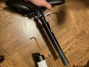
    • Unscrew the seatpost clamp screw with the 5mm hex key

    • Remove the seat and seat post

    • Pull off the seatpost clamp

  3. bQ6jDF5yfjxQANxv
    bQ6jDF5yfjxQANxv
    6OJ3xvhuemOZUlDF
    BBXUDjttYMA6qBmy
    • Remove the crank arm bolt with 8mm allen key completely

    • A significant amount of pressure may be needed at the beggining. You may hold the crank arm for better force

    • Before removeing the drive unit its best to check this video for a general overview: https://www.e-bikeshop.co.uk/Bosch-eBike...

  4. MCmJ4bNq5ptd3VwT
    MCmJ4bNq5ptd3VwT
    a1xInX3MIhaTUrDu
    53XOorevDTFOKycw
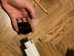
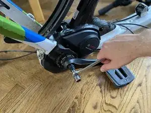
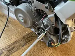
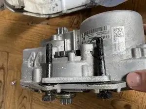
    • Install Crank extractor tool

    • screw the extractor tool gently in

    • it is designed to go in nice and smooth, by hand!

    • hand tighten the rear portion of the crank extractor

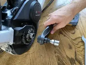
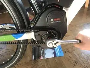
    • With the 16 mm wrench rotate clockwise

    • Remove the extractor tool

    • Repeat on the other side

  5. vmKCFybn64JR1HOt
    vmKCFybn64JR1HOt
    tMD3KasYROU3blTB
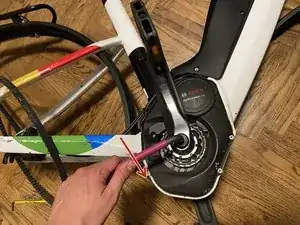
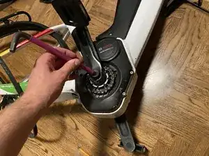
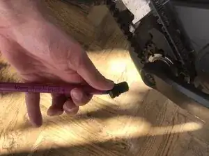
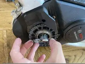
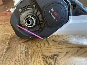
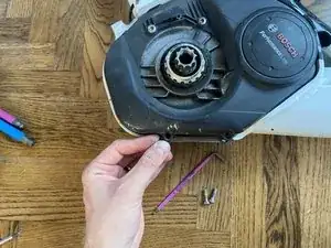
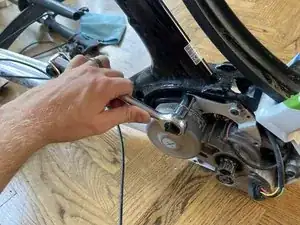
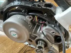
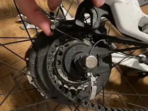
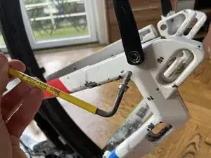
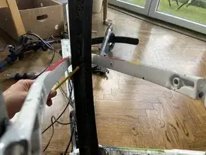
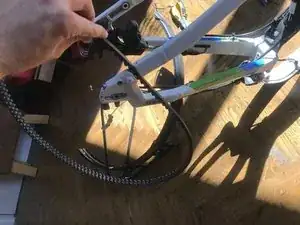
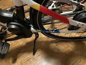
    • Hold the back brake (or hold it in place with a zip tie)

    • So the back wheel cant move, and the carbon belt holds the chain ring in place

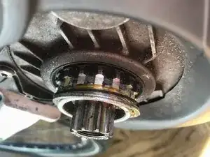
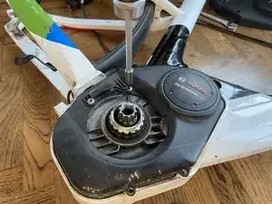
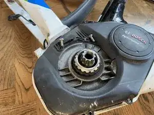
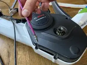
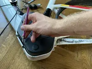
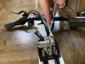
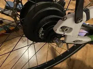
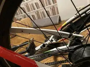
    • with the Bosch chain ring lock ring removal tool on a 1/2" ratchet loosen the lock ring on the chain ring

    • To loosen one needs to turn it to the right! (clockwise) [it is the opposite direction than usual]

    • A significant force is needed to loosen the lockring

    • In a later step, after the carbon belt is removed, the chain ring can easily be pulled down too

    • The text must face outwards both on the chainring and the lockring

  6. XISGZtCbt1ZWdOeI
    XISGZtCbt1ZWdOeI
    BXPuffqfBZIgZ2CZ
    4XKoq1oLKltBVPMm
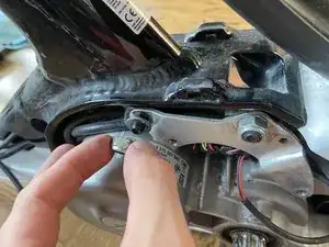
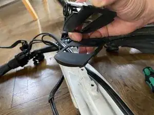
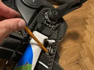
    • With the help of a Philips 1 screwdriver remove the tiny screw holding the plastic guide in place

    • After the screw is removed the plastic can be slid off to the side

  7. 3gPZt5Chs6dLtvVe
    3gPZt5Chs6dLtvVe
    BYaDJUqMTp4eUBHr
    hPZiSjgYrVoaQktO
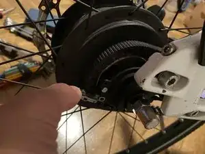
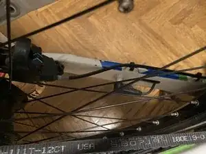
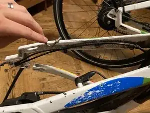
    • Loosen the back wheel bolts with the 15mm wrench on both sides of the rear axel and move the rear wheel out vertically for a few centimeters

    • Thus no tension is on the belt

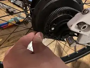
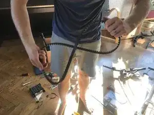
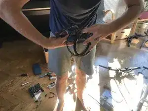
    • slide the belt and chain ring off the drive train axel

    • Do not put too big force on belt (bending etc)

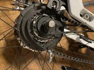
    • Slide the remaining double metal ring off

    • Slide the underlying black sealing ring off
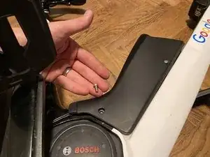
  8. vAJsCvyRnl3XICPU
    vAJsCvyRnl3XICPU
    SZwsNQlVHUXhwCrl
    RAP2F4WXncOCEgcH
    • On the right side:

    • Remove the 2 screws closer to the front with the help of a 3mm hex key

    • When the plastic is a bit loose, a black plastic distance holder can be slid out from between the frame and plastic cover

  9. NUi5eTou3JYLopQE
    NUi5eTou3JYLopQE
    WSPxNSkDgQKEvMob
    IBLxbiSxZUQXfsCL
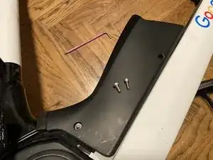
    • Proceed using a T25 torx screwdriver to remove the 2 screws holding the plastic cover in place on the right side of the frame

    • approximately where earlier the belt placeholder was

    • After all these screws (4 in total on this side) are removed, the plastic cover can be lifted and removed

    • Proceed to the other side

  10. XBhruWWtRms2nEpO
    XBhruWWtRms2nEpO
    PX32pviLRXJZfZos
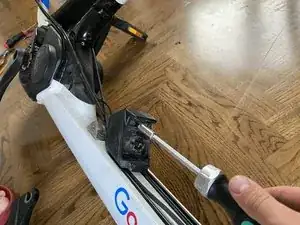
    • On the left side of the frame:

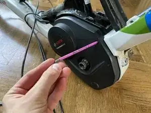
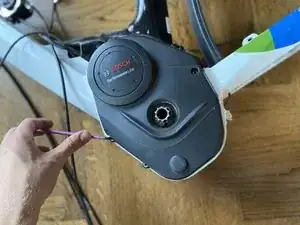
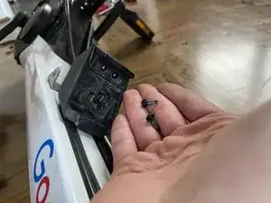
    • Using the 3mm hex key, remove the small screw in the deep hole

    • This screw has a length of 11,5mm

  11. I6jcKjx1jLXlyHMP
    I6jcKjx1jLXlyHMP
    Vc515KPHHHoDUKwh
    dL1bcylwsCV5qWjV
    • Remove the two (identical) lower screws with the 3mm hex key

    • On this bike type, the frame could take bigger screws, thats why the first screw has a longer "neck". In one case this came out directly, when unscrewing the screw.

    • If this extra does not come out, then it can be removed with a big flat head screwdriver (size 8) later on, but must not necessary be removed

    • These screws are 17,5 mm long

    • Lift off the plastic cover

  12. NuSsWZPHvFvk5VCC
    NuSsWZPHvFvk5VCC
    iACBTc4wB5d24GrK
    OIsv5WyElXAJHWDS
    • Since the frame holds the unit in place, the drive unit holder screws can be removed before the cables are

    • However, make sure, the drive unit does not fall out of place!

    • Remove the two torx screws with a T30 torx screwdriver

  13. qmOAosbAKoXXUOhI
    qmOAosbAKoXXUOhI
    VqCOqMnwxHdHMCnE
    yyNlUr3AjJCOVHPD
    • Remove the two nuts with a 13mm socket and ratchet

  14. LdqBjL4D4rfDeers
    LdqBjL4D4rfDeers
    LsVEhSg3UcEJZDhF
    CARbUOJnxPPoPnxt
    • Never pull directly on the cables!

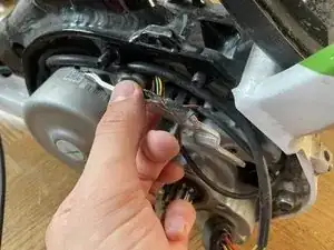
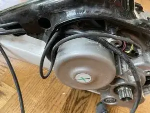
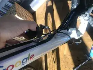
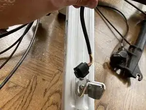
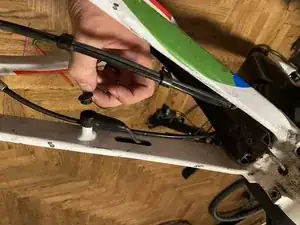
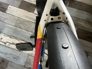
    • Remove the biggest cable, the battery cable:

    • Using a flat head screwdriver loosen the catch 1-2mm

    • Using pliers disconnect the plug of the powerpack

  15. MBd4r4rGogW5qdeE
    MBd4r4rGogW5qdeE
    YFjnvlmB2IrhAM6Y
    • These images show how the original cableing was and serves as a reminder of all 4+1 plugs in place (battery pack plug is disconnected already)

  16. NaK2QvFjAqXQgCED
    NaK2QvFjAqXQgCED
    5PqbHb5SOZQIMJJS
    dGnNG1ZmJZ6tG5rc
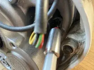
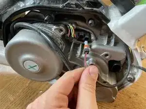
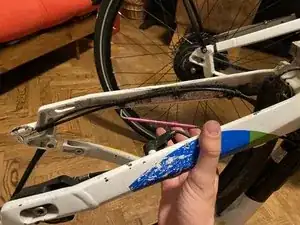
    • Located in 3. place from the left is the back lamp's cable and plug

    • It runs directly to the back of the bike and exits the drive units frame part on a hole around the kickstand just below the rear fender

    • The cable runs through the inner side of the rear fender and ends in the back lamp

  17. PnPk54BUm4LpWGd1
    PnPk54BUm4LpWGd1
    f1vSd5CYan15hEqe
    HQeUQP3V6AlEgycP
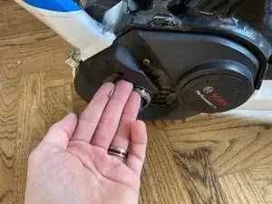
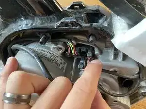
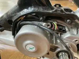
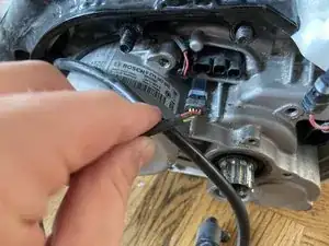
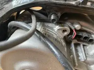
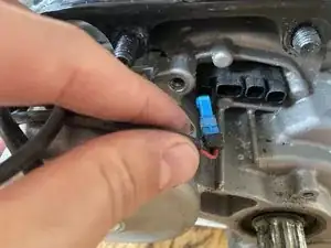
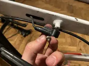
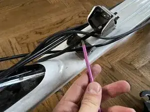
    • From the 4. socket remove the plug of the bosch sensor

    • The cable goes directly inside the left back fork and exits just before the sensors place

  18. o1Xok6shyt32MNNk
    o1Xok6shyt32MNNk
    nSr4SERJWVROJS1M
    mM2dWK6TaJKRJxpQ
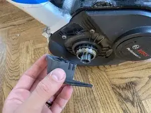
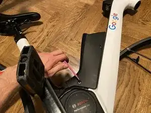
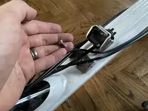
    • Remove the flat plug and unwind the cables

    • The cable enters the inside of the frame in the middle and exits on the left side on the biggest hole, runs up the frame and to the board computer mount

  19. VkEFmARW3L6EQBBx
    VkEFmARW3L6EQBBx
    6L2sv3BwmV6WXpG5
    BxQfuQR2eTIr4YdN
    • The first socket is for the front light and goes straight throw the middle of the frame, and out on the biggest whole

    • Runs along the fork and up to the light

  20. ivP6bxYqX5WwFLAG
    ivP6bxYqX5WwFLAG
    VEahZsiEDGDqgZCC
    r5lUHQpgTaT3Rr4U
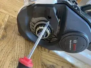
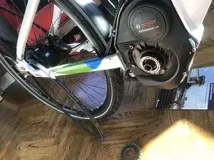
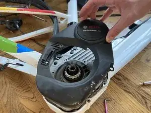
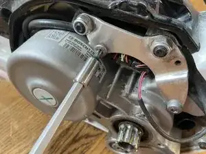
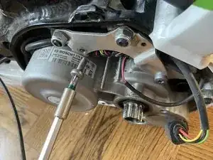
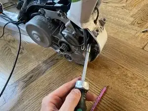
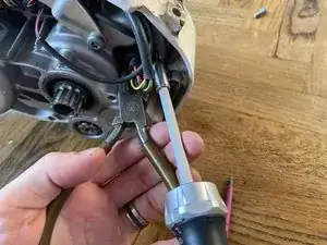
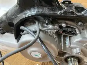
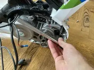
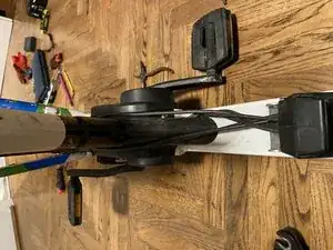
    • When all plugs are unplugged, the last nut can also be loosened with the 13mm socket

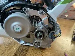
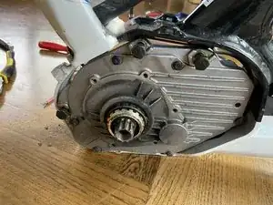
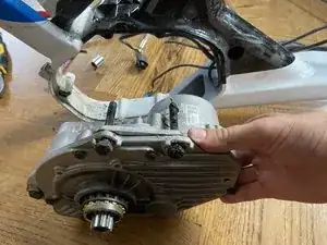
    • The drive unit can be shifted horizontally to the other side.

  21. eEyPaKUEAECsGfDk
    eEyPaKUEAECsGfDk
    24pBFBFirQy4C4uc
    • Keep the long place holder on the two long screws on top of the drive unit

    • Keep small place holder on the lower long screw as well!

  22. PF2FBaCmbpaVyniZ
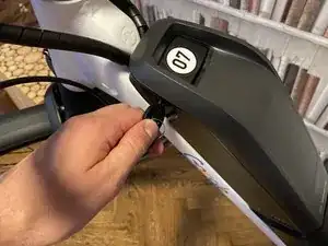
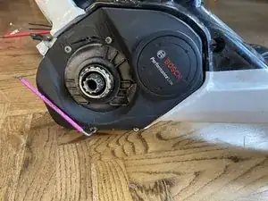
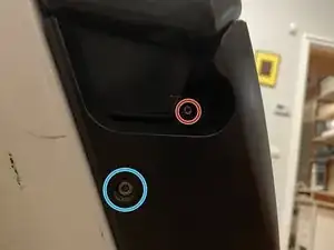
    • Remove the screw next to the battery charging port with a PH1 Screwdriver [marked with red circle]

    • This screw is the smallest of the three types

    • Remove the upper screw with a 3 mm hex key on both sides. (2x in total) [marked with blue circle on this side]

    • These screws are slightly longer and thinner, than the lowest screws

  23. tSSAjCmfsq3dIlke
    tSSAjCmfsq3dIlke
    PoEulO5OSfyNyhNM
    kligjM1TZDr1HYV3
    • Remove the lower screw on one side.

    • This lower screw is thicker and shorter, than the upper hex screw

    • The screw on the other side can also be removed, however its better left and simply shifted to the side (there is a spacer inbetween held in place with these two screws)!

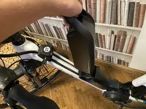
    • After the 4 screws are removed, the black cover can be taken off (comes in two pieces) sideways

  24. 5dLtLGTjMZWc4ykf
    5dLtLGTjMZWc4ykf
    gM5ZxRA3MYMHgIUH
    kMcQYYAUXmgNEqcv
    • For removing the plastic cover of lower battery holding part

    • Remove the two black screws from the black plastic with a T15 torx screwdriver

    • Release the catch on the lower side (facing the back fork/drive unit)

    • By taking the plastic parts apart, the outer shell can be removed

  25. hwAZxKEsXZvB3dpx
    hwAZxKEsXZvB3dpx
    XQdclyJkSysCK6wW
    g3euP6M1qwYfQlCM
    • First remove the cables with smaller plugs through the rectangular hole

    • Carefully, not to bend (and break) cables and plugs

    • After all other cables removed, the battery plug fits the big hole on its own

  26. eOmsSPvXOTCIvReY
    eOmsSPvXOTCIvReY
    AcAGIoKyZTQgSsW5
    • Remove the two torx screws with a T25 torx screwdriver

  27. OePUFBPkQFutJ45C
    • For the upper cover

    • Using the T15 torx screwdriver remove the black screw from the low end

    • lift the cover gently (lift outwards around the lock)

    • after fidgeting around, lifting the right side helped

  28. S6pNjUVnUfq5qdZl
    S6pNjUVnUfq5qdZl
    asWBqJFtekS2eLJF
    HRULTGhlMxCXnxS1
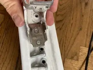
    • With the help of a T25 screwdriver, remove the two screws holding the upper (locking mechanism) to the frame

    • When both screws are removed, the lock can be lifted (removed)

    • The plus is on the upper side

    • Underlying cable holder plastic can also be lifted

    • the higher fences show to the upper side, also the narrower side is on the top

    • There may be a plate under the lower screw between the frame and the lock (10)

    • But could also be below the upper one (04)

  29. fULkMybpsaaYInPF
    • Remove grip on right side

    • Loosen the brake lever and pull it off the handle

    • Alternatively unscrew the holding part on the fork with 3mm hex key

  30. Ytk6hpLrlXZEQuVp
    Ytk6hpLrlXZEQuVp
    PNe3VbZXvRj15HPc
    dLTrgDuQXBtedKwv
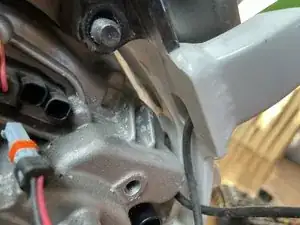
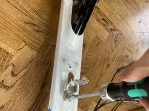
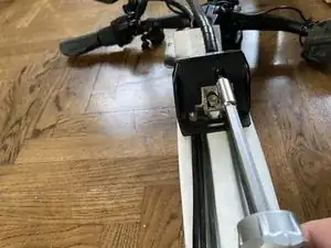
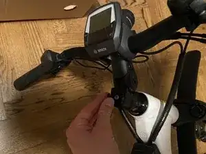
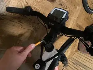
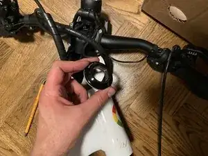
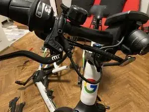
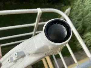
    • Remove - if any - protective/design rubber cap on stem

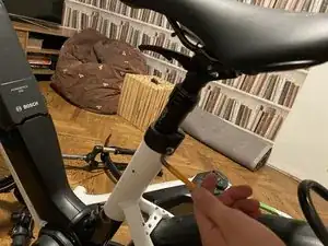
    • Loosen the stem with a 5mm allen key.

    • Loosen the two bolts on the side of the stem with the 5mm allen key

  31. uuWEkbddMTcoZPuT
    uuWEkbddMTcoZPuT
    hbJaO66gyJM5WEFC
    qKOoCFrhVVEh2Cud
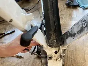
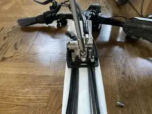
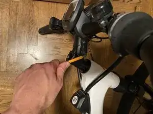
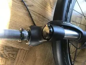
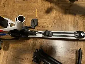
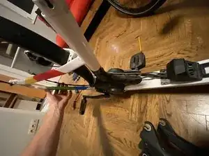
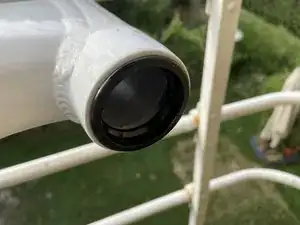
    • Carefully lift the handle bar off the fork

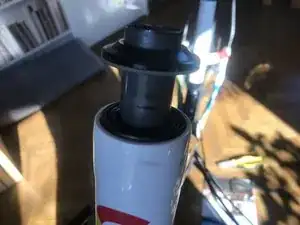
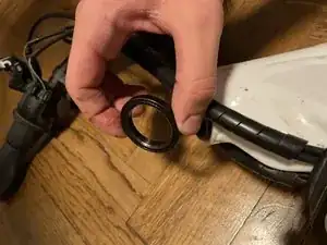
    • Lift the two consecutive spacers off

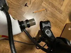
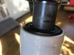
    • Lift off the bearing cap

  32. BQcEKSZSOxgYbmBR
    BQcEKSZSOxgYbmBR
    ho6ycGaOmHNXjWRJ
    mTIAVYD4EDIhjPrF
    • Remove upper bearing

    • The flat part must be facing upwards, the cornered part downwards into the frame

    • The lower bearing can be left on the front fork

  33. FEbVpShDPObMcMUX
    FEbVpShDPObMcMUX
    Ytgwe2dGfgRDJ2cb
    DWkkNRoVq5PFisxS
    • shift pedals to a position that allows easy access to the shift cable hardware

    • Remove the shift cable hardware ends

    • Open the securing closing mechanism on the lower one (open and lift)

    • Remove the cable end from its socket

  34. RXErGRiIcBmYmYrl
    RXErGRiIcBmYmYrl
    kf6mmXDQWaHRODyc
    • Remove the upper cable's end from its socket

    • The cable with no closing mechanism comes on the top part, and the closing mechanism closes in from the bottom on the top

  35. ByWpM6kBiyChfolT
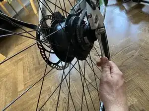
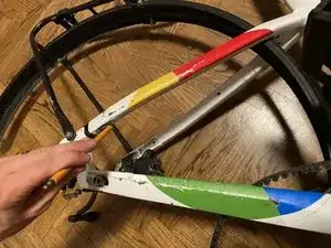
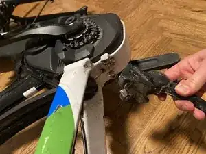
    • Loosen the bolts with the 15mm wrench on both sides of the rear axel

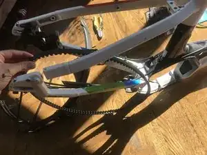
    • Remove the rear wheel carefully, not to damage the belt!

  36. fWro1aC4PQAEJ3vQ
    fWro1aC4PQAEJ3vQ
    IFyCVgsrxwFsWGp3
    • Remove rear facing bolt with 5mm allen key

  37. fhWBawyciQLxSktq
    fhWBawyciQLxSktq
    LXguAEtULXmNZujB
    • Slide the black part out of the frame (pointy part faces backwards)

  38. X3XvuJTNjoQRs2LB
    X3XvuJTNjoQRs2LB
    rmamAMwdrj2GFlPI
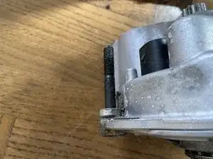
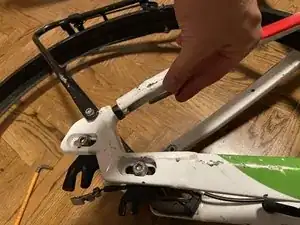
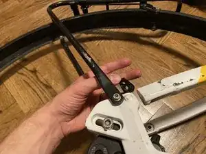
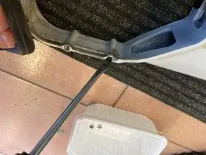
    • To remove the bolt that held the long screw and black part in place,

    • use a small but long tool (nail or screwdriver) and put it in the hole, where the removed screw was previously, but not through the upper part of the frame, but diagonally from the outside - thus the bolt can be slightly pushed out of the frame

    • Grab this slightly outlying bit with a plier and pull it out

  39. 3RmplfEuNkv4rbHg
    3RmplfEuNkv4rbHg
    yMCvj6AHQwtPhbiC
    • Do not remove the bike rack (the mud guard) while the back light is still attached to the motor!

    • Loosen the two bolts on the rear part of the frame with 4 mm allen key

  40. N2HryvFd1YEr3SXD
    N2HryvFd1YEr3SXD
    DJrxCBrMulwVTD4m
    KE3nT5BrVQAaWVP5
    • The Bolt has multiple plates:

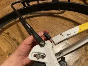
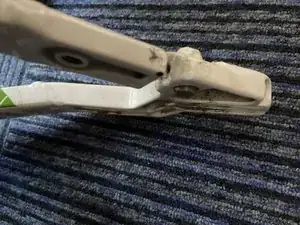
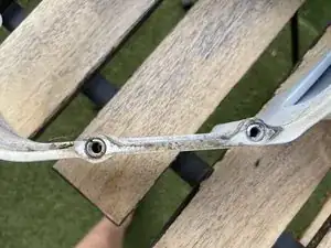
    • a metal plate below the bolt head

    • a cornered black plate , then comes the bike rack

    • one metal between the bike rack and the frame

    • Main goal is to strip everything from the frame, thus the rest of the bike racks screws do not have to be removed, since the complete bike fender must be removed

  41. L2TWoWiQYINiWSLw
    L2TWoWiQYINiWSLw
    kwBoNqjIvqMnnDI4
    NaIGK2TpHtnA5MkG
    • Remove the two screws holding it to the frame's middle (back frame's triangle's corners)

    • There are two (1-1) black plastic/rubber plates between the fender and the frame on the screws

    • In total the bike rack and rear fender are connected with 4 screws to the frame

  42. lXL3YWJX1LDrAA5h
    lXL3YWJX1LDrAA5h
    3LsiUiUOxAytqZPH
    • Carefully remove the Belt through the frame

    • Watch out not to bend the belt, or damage it in any way

  43. 3rZDBMJkJqARFWSg
    3rZDBMJkJqARFWSg
    hQIEVKEOHjc1Uqdq
    PGhadNVx6vDWHBYX
    • For storage purpose you can coil the belt by holding it on the two sides, and turning one hand inwards, the other outwards.

    • If you feel resistance, STOP!

    • It should coil easily (in three loops)

    • This video shows the process: https://www.youtube.com/watch?v=VgM-qeHG...

    • Uncoiling: find the outermost circle, and slowly start to straighten it out. The Belt will uncoil on its own

    • If you feel resistance, STOP!

    • Uncoiling the belt: https://www.youtube.com/watch?v=slFf0q1I...

  44. byOXhF3lW6kmFXvZ
    byOXhF3lW6kmFXvZ
    rUtpSbkvKVTloLpQ
    oD6DEEsGWcQ6pWSo
    • Loosen the two front facing bolts with the 5mm hex key

    • Curved side must face backwards (obviously, as the stand must look backwards...)

  45. 2KlPxct1vUs66YpN
    2KlPxct1vUs66YpN
    YTxbTTCUsnnWsTxA
    nS6OAehbeGsjqvE2
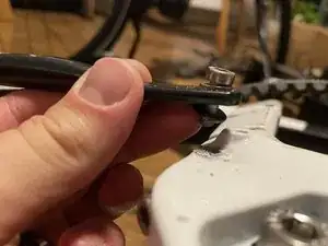
    • Remove the longer front facing screws (with neck) from the rear end on both sides with 4 mm hex key

    • those setting the tightness of the belt by adjusting the position of the wheel holder

  46. OPee6olaemQKHKfi
    OPee6olaemQKHKfi
    pT2JbAMW4PGCXUGE
    bNAoqIvC4MjCwb5S
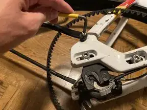
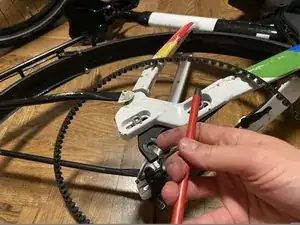
    • Cut the zip ties holding the brake cable on the frame with a wire cutter or remove other fixating elements

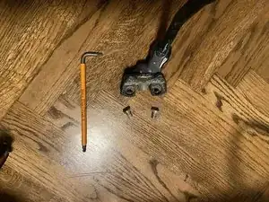
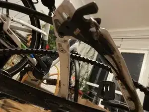
    • Remove the screws on both sides (2x2) holding the wheel holder in place with 6mm hex key

    • The plate comes between the bolt head and the frame!

  47. twBrZuVMVvY6b1Rj
    twBrZuVMVvY6b1Rj
    mZvSDNUojtUmtxo1
    YPJX6PQmGdZ33OqT
    • Remove the rubber cap by hand

    • Remove the locking screw with a T20 torx screwdriver

    • The speed sensor's cable is going through the frame

  48. a4aCgoIant1jfxmb
    a4aCgoIant1jfxmb
    fi6Tg2UL2XFWqyB1
    W2XetxMePA1MyyT6
    • The rear break levers' "cable" (on the right) is tied together with the Intuvia board computers fat cabel and goes down the frame on the right side

    • After the Battery, it crosses and exits the black part on the left side (as single cable) and goes on the top part of the rear frame

  49. yI2FPVtLXZ2FDORG
    yI2FPVtLXZ2FDORG
    AAnT5R36vnLDYnJH
    sTIlMhYrJd2M2sN2
    • The NuVinci gear shifter is on the right side.

    • The cables are tied together with the supernova lamp's thin cable (in comparison to Intuvias thicker cable) .

    • These cables go down on the left side of the frame. Then cross under the black part below the battery and exit on the right side (only the two Nuvinci cables from here). Then it goes down to the inner part of the frame's back triangle and has three plastic holders.

  50. NWGSyUlCcxxiyWKR
    NWGSyUlCcxxiyWKR
    GFVrPgGEgscABsE4
    • Remove the 3x screws, keeping the cable holders in place, with a 3mm hex key

    • The frame is upside down for easier work conditions on the image

  51. AU2WuPCMptU4cuD4
    AU2WuPCMptU4cuD4
    sS4fOEPSX5HiqmAB
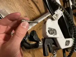
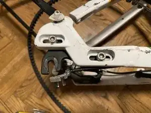
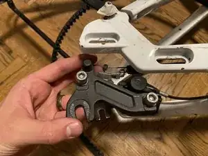
    • Underlying metal holder (and cable aligner) is held in place by a 3mm hex screw

    • A big diametered washer is under the screw head

    • Below is the placeholder

  52. UnPaEeSvlI4fnKGO
    UnPaEeSvlI4fnKGO
    mvZaVKkBMvNea1Kt
    tGK4a2ZW1ihGW2GQ
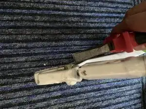
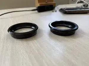
    • The one on top has sharper corners

    • The one on the bottom is fully rounded

    • They can either be removed with a specific tool, or with a chisel and a hammer (possibly rubber hammer)

    • Be careful with this step not to damage the rings inner side - might even ask for the help at a local bike shop

  53. Y6qOXJccQBtjfQLE
    Y6qOXJccQBtjfQLE
    LmAaEMERwCrlD5Ys
    JwGCeEQsf5UMrCZc
    • Before painting the fork these small parts can be removed with a wide flat head screwdriver (8), but do not have to necessarily

    • This step can be skipped, especially, because these can easily be damaged, and are sometimes difficult to remove

  54. EQgx6XtgB1vFUNeu
    • Check with paint shop if the wholes should be protected

    • If needed - insert (short) screws in all places, where there were any before, to save their guideway (14 small type screws, 7 bigger type)

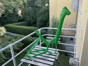
    • And the frame is ready for a fresh new paint!!!

  55. Nchwca3YmYA4oZSl
    Nchwca3YmYA4oZSl
    YwFfKcT3TeDelQjF
    qMZQEqYEFkZDFjfV
    • There are 2x2 unused bolts on either (inner) side of the frames back triangles top tube

    • Additional two unused bolts are just over the rear fender facing slightly upward

Conclusione

To reassemble your device, follow these instructions in reverse order. Except for the nuvinci cable setting - this has to be adjusted at the end, when the back wheel is set to the right position and belt tension

Bango Bejla

Membro da: 08/11/16

1357 Reputazione

2 commenti

Do you have any photos of the frame after it's been painted?

Rares Alexandru Murza -

Yes, I updated the main picture to show the frame after the paint job :)

Bango Bejla -