Introduzione
The camera turned to be not weather-proof. After a day in heavy rain, enough water seeped, apparently, through the battery compartment, and it refused to turn on. Fuji service centre refused to make repairs to a camera with water damage. No other workshop was ready to do the job. So I had to do it myself.
Strumenti
Ricambi
-
-
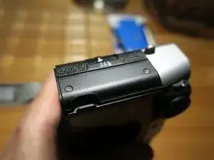
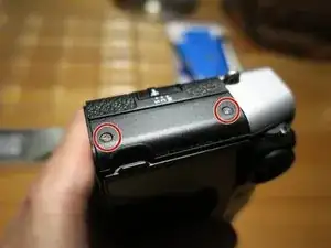
Peel off leatherette on the back left side, near the LCD and the viewfinder. It reveals two screws.
-
-
-
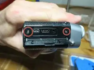
Unscrew two screws.
-
Carefully pry off the port cover panel together with the flap cover. Try not to damage the spring.
-
-
-
Open the LCD panel
-
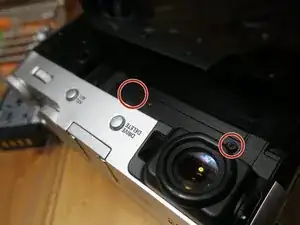
Unscrew two screws near the top
-
Note that they are of different length, the one near the viewfinder is longer.
-
-
-
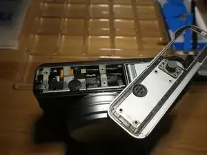
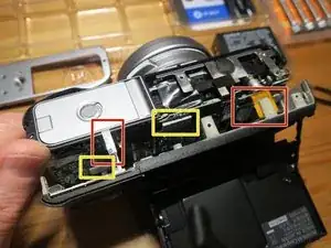
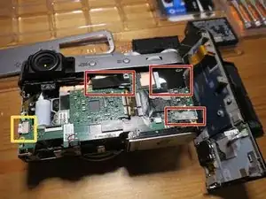
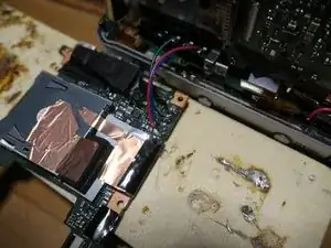
Carefully pull the cover out. It may be held by the two blocks of thermal paste (yellow markers).
-
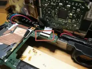
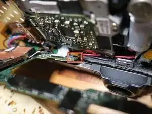
Pull off the white ribbon cable. Before pulling out the orange one, unlock the bar on the connector. See red markers.
-
Use a thin tip spludger to unstick rubber foam near the viewfinder that may be holding the back cover.
-
-
-
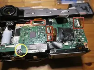
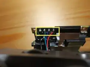
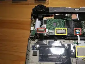
Peel off black (and one white) sticky patches that cover connectors.
-
Remember which patch goes to which spot.
-
Pull off the white ribbon cable (yellow marker)
-
Unlock and disconnect orange cables.
-
Unsolder the speaker.
-
-
-
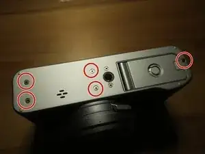
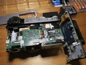
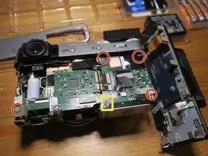
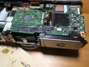
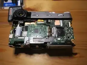
Unscrew four screws
-
Slightly bend the board to release it from the plastic hook (yellow marker)
-
-
-
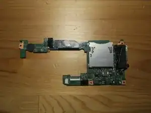
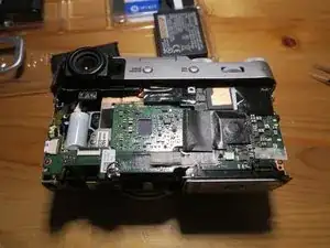
Peel off the round foam pad and all patches and reattach them to the replacement motherboard.
-
Be careful with the patch with copper foil (not on the picture), it is fragile.
-
-
-
I am rather ashamed, but hey, it works!
-
My Hakko FX888D could not sufficiently heat the pads, I had to use a bigger soldering iron.
-
-
-
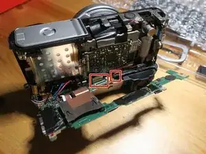
Connect and lock the wider cable
-
Insert the narrow cable. It is rather fiddly, you need to push it from the side with a pinzette.
-
-
-
Push the board in place and under the hook.
-
Connect and lock all the numerous upper side ribbon cables.
-
Solder the speaker
-
-
-
Put the back cover in place.
-
Carefully bend out the spring of the port panel cover and put the cover in place.
-
Screw six screws that hold the back cover.
-
Close and screw the bottom cover
-