Introduzione

  1. aAUZZHquFKtTeUqW
    aAUZZHquFKtTeUqW
    3CAOaGXV3YTXiala
    • Be sure to turn off the Dash Cam by pressing the power button.

  2. XhoDtg1fAOVNKaYY
    XhoDtg1fAOVNKaYY
    GDrJ233xnlsvjRk6
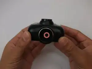
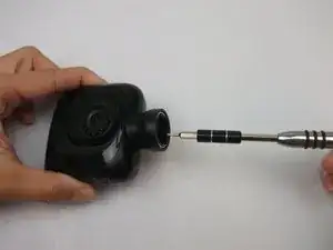
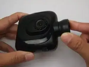
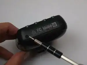
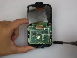
    • Rotate the Dash Cam to where the socket faces you.

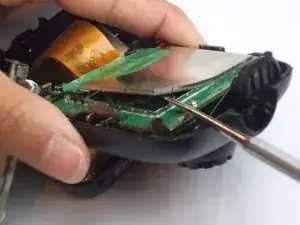
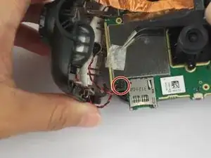
    • Remove the 9 mm screw using the Torx T6 screwdriver.

  3. TVWp2O5QcQkMNyD3
    TVWp2O5QcQkMNyD3
    1EFIMOaFGxGMRNBv
    • Remove the Dash Cam socket piece.

  4. jRvlnbBoWNutfIQf
    jRvlnbBoWNutfIQf
    fCRpdudxDksQTFsw
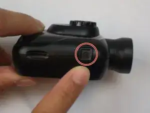
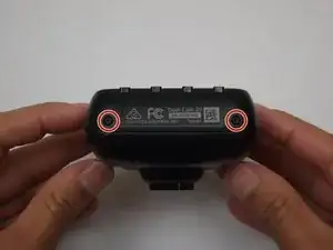
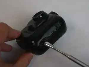
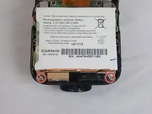
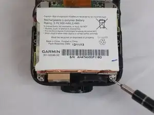
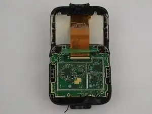
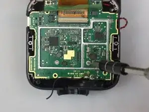
    • Rotate the Dash Cam to where the product information faces you.

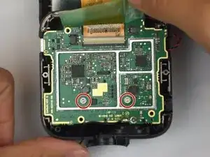
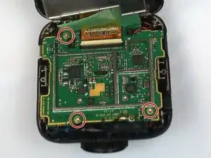
    • Remove the two 5 mm screws using the Torx T5 screwdriver.

  5. cSAIJknpDoOLh5or
    cSAIJknpDoOLh5or
    xPb5qWucM4HhcOCg
    EVvZqJiBWLYvqyKf
    • Remove top case from the bottom case.

    • The compact nature of the casing requires use of the metal spudger for needed leverage.

  6. J1oZQEoYQbhFOhLN
    J1oZQEoYQbhFOhLN
    KqAR2sNKlJHFkTrC
    HSMUZdIskTAKP3JJ
    • Remove the two 5mm screws using the Torx T5 screwdriver

    • By removing the screws, the metal battery frame will now become free from the rest of the device.

  7. 1xdl1VLBXMIYH2HZ
    1xdl1VLBXMIYH2HZ
    uCZMMjyvotDVVgAd
    • This step shows the use of an incorrect tool. Always use an ESD safe tool, like a nylon spudger, when working with delicate internal components.

    • Use the nylon spudger to pry the corner of the case off of the motherboard.

  8. 5IBJiC5iVAfuLQCh
    5IBJiC5iVAfuLQCh
    GPTUEv613qQ6ESPo
    xEMOY46R6kQNXVjc
    • Remove the metal case off of the motherboard.

  9. GET4LBdhwRHlJB6U
    GET4LBdhwRHlJB6U
    ATVJHvrgsZAeAIWk
    yGcrdCSIN23LqW1X
    • Remove the battery connection.

  10. YiFEb2yCJyUcBMV5
    YiFEb2yCJyUcBMV5
    3KQ5HkjqEeiCaLyu
    AUCTIRuTNv5lLMgL
    • Remove the three 5 mm screws using the Torx T5 screwdriver.

  11. 2C2kM1QIBrl3XY3d
    2C2kM1QIBrl3XY3d
    TyCRZMQqUw1uBaSn
    VOVq2vmpOnL5YMPG
    • Use tweezers to remove the connector on the top right of the motherboard.

  12. 6Nnq6CbcDrsUibhA
    6Nnq6CbcDrsUibhA
    Ay35ImUrAFXT31WR
    Dm31bjlSYGlDiabr
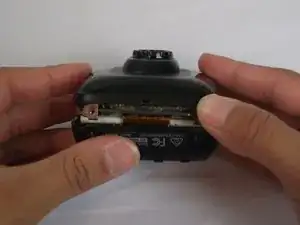
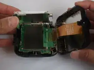
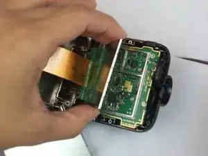
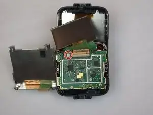
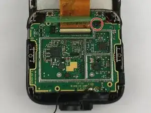
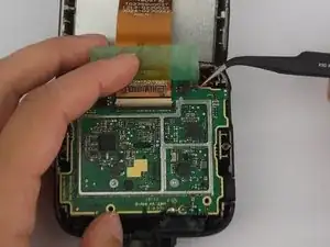
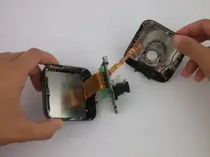
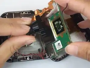
    • Remove the motherboard from the case and flip to reveal SD connection.

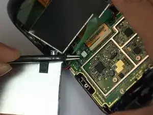
    • Use tweezers to remove the connector next to the SD card slot.

  13. XiAUHq2ehLPXMGyl
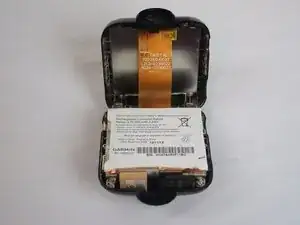
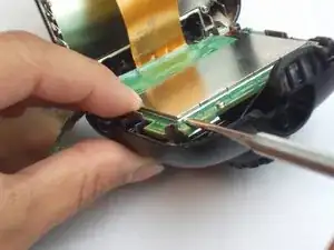
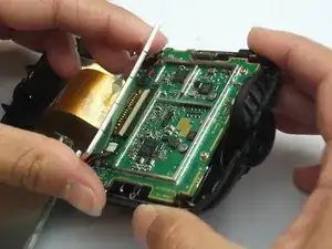
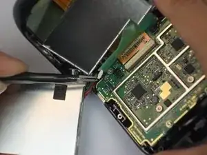
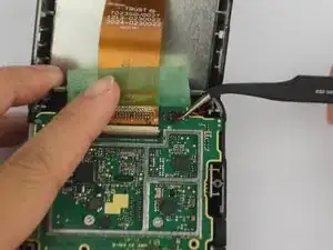
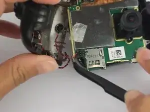
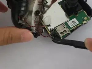
    • The motherboard is now removed aside from the copper strip and its connector.

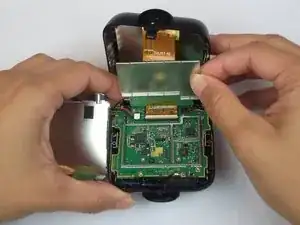
    • Disconnect from the front case and the copper strip.

  14. RHHEWAiSwMkQSW5p
    RHHEWAiSwMkQSW5p
    NSNGNaYtaCdDDKlO
    • Use the Torx T5 screwdriver to remove the two 5mm screws.

    • These screws hold the camera in place. Therefore, the lens will fall into the bottom case.

  15. AFtXPsm5cH1HuJw5
    • The camera lens is now detached.

Conclusione

To reassemble your device, follow these instructions in reverse order.

Jesse Hillman

Membro da: 04/10/16

757 Reputazione

0 commenti