Introduzione
Solid state drives contain no moving parts, unlike a hard drive, and can last for years. One might want to switch from a hard drive to a SSD or purchase a bigger storage SSD. This guide will walk you through replacing the SSD card inside the motherboard.
-
-
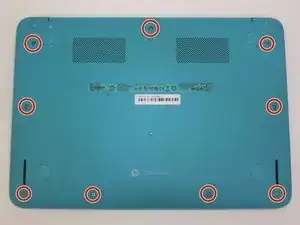
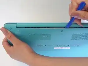
Turn the laptop over.
-
Remove all nine 3mm screws on back panel with a Phillips Head 1 driver.
-
-
-
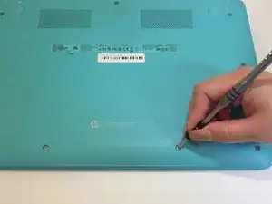
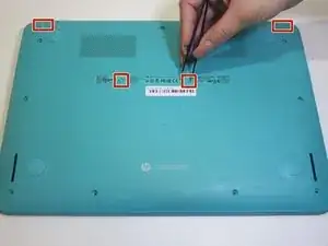
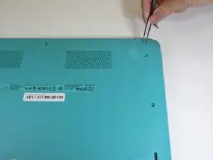
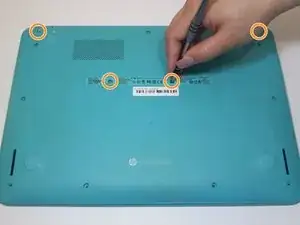
Pry off the four rubber bumpers, located at the top corners and center of the back panel, off with a pair of tweezers.
-
Unscrew the four 3mm screws under the bumpers using a Phillips Head 1 screwdriver.
-
-
-
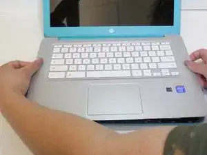
Flip the laptop right side up and open the clamshell.
-
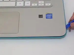
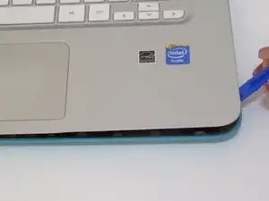
Starting at the bottom right corner, slide the opening tool into the crevice between the blue and silver panels.
-
Carefully pry the top casing up around the edges, moving counterclockwise.
-
-
-
Close the laptop and orient it on its side (clamshell hinge up), carefully holding it steady to ensure its safety.
-
Insert the opening tool inside of the hinge and pry with an even amount of force to disconnect the keyboard panel from the fan grate.
-
-
-
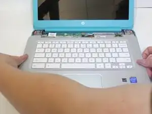
Reorient the laptop in an upright fashion and open the clamshell.
-
If needed, continue to pry the silver keyboard panel from the rest of the hardware with minimal force.
-
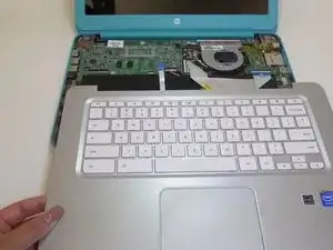
Slowly slide the silver keyboard panel towards you while lifting gently to separate the halves.
-
-
-
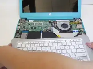
While keeping silver keyboard panel hovering above the laptop, locate the touchpad connector ribbon attached to both the silver panel and motherboard.
-
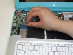
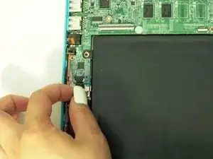
With your finger, flip up the white clasp that holds the connector, releasing the connector ribbon.
-
Unpeel the connector ribbon from its position on the motherboard.
-
-
-
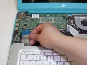
With your finger, flip up the white clasp that connects the larger keyboard connector to the motherboard, releasing the connector ribbon.
-
Gently pull the connector ribbon from the clasp.
-
-
-
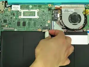
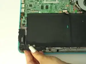
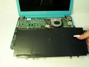
With the internal hardware exposed, disconnect the battery cable from the motherboard.
-
If tightly fastened, gently wiggle the plug out of the jack.
-
-
-
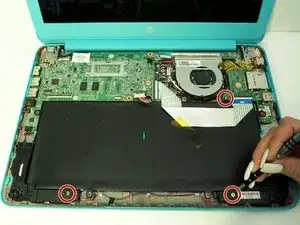
Remove the three 4mm screws around the perimeter of the battery pack with a Phillips Head 1 screwdriver.
-
-
-
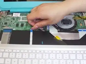
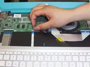
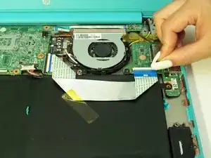
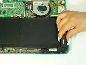
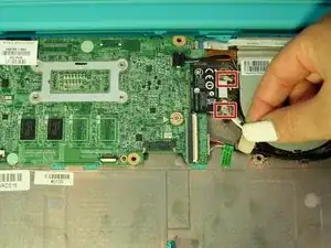
Flip up the two white clasps that hold the connector ribbon to the battery to release the ribbon.
-
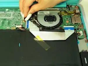
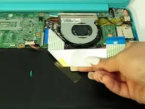
Remove the 'motherboard to USB board' connector ribbon from its place.
-
-
-
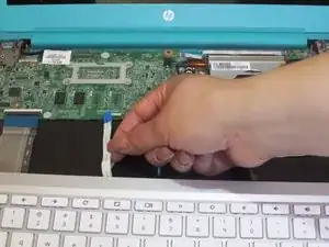
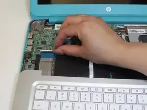
Detach the speaker cable from its fastener on the motherboard by pulling it out with your fingers or using a spudger.
-
-
-
Using your fingers, gently pry out the two L-shaped speaker panels from between the external casing and battery pack.
-
-
-
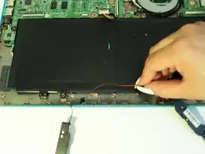
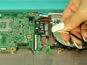
Remove the two Wi-Fi antenna cables that are attached to the Wi-Fi card by pulling them up.
-
-
-
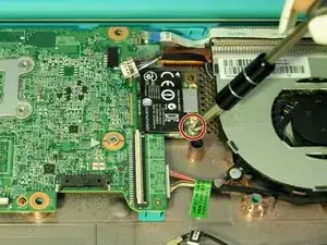
Remove the 3mm screw that holds down the Wifi mini-PCI card using a Phillips Head 1 driver.
-
-
-
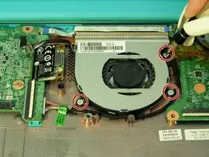
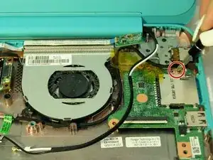
Remove the three 3mm screws that hold the cooling fan in place using a Phillips Head 1 driver.
-
-
-
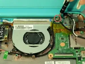
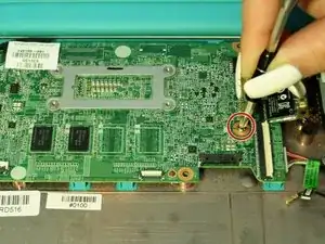
In the upper right hand corner of the device, remove the 6mm screw holding the PCB board in place by using a Phillips Head 1.
-
-
-
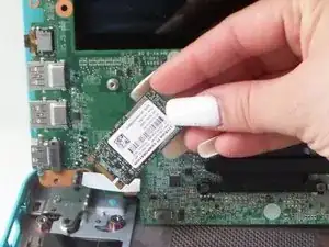
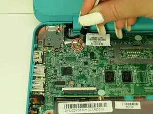
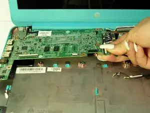
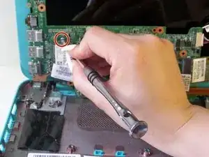
Remove the 3mm screw located directly above the NGFF SSD card using a Phillips Head 1 driver.
-
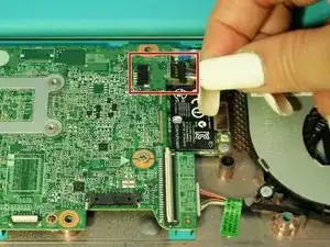
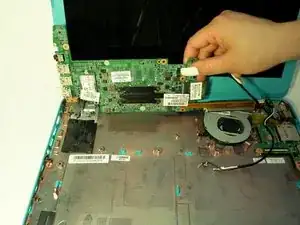
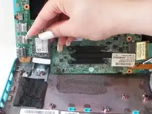
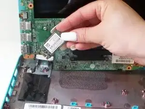
To reassemble your device, follow these instructions in reverse order.