Introduzione
-
-
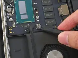
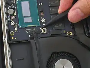
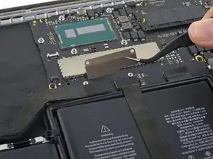
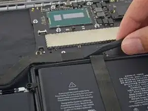
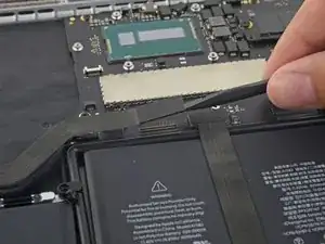
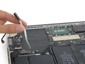
Use the tip of a spudger to push on either side of the the iSight camera cable connector to walk it out of its socket on the logic board.
-
-
-
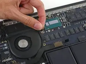
One of the screws holding the top shell of the fan assembly is hidden just behind the I/O board cable.
-
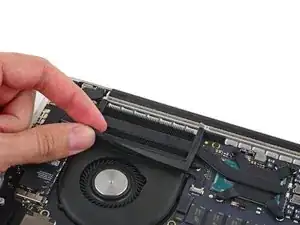
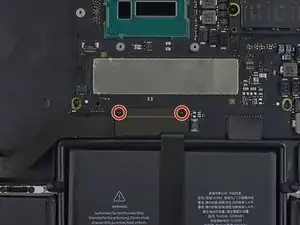
Remove the two 2.1 mm T5 Torx screws securing the I/O board cable bracket to the logic board.
-
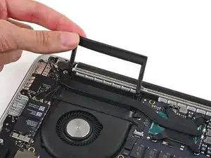
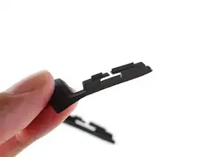
Remove the I/O board cable bracket.
-
-
-
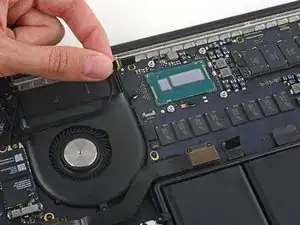
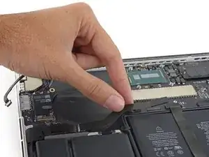
Use the flat end of a spudger to pop the I/O board connector straight up off its socket on the logic board.
-
-
-
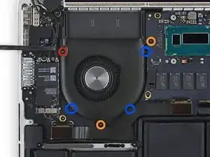
Remove the following screws securing the fan assembly cover to the rest of the assembly:
-
One 5.0 mm T5 Torx screw.
-
3 Phillips #000 screws.
-
Conclusione
To reassemble your device, follow these instructions in reverse order.