Introduzione
If the cameras in the Infant Optics DXR-8 are not properly functioning, the motherboard may be faulty. Follow these instructions to replace the camera motherboard in the device.
In order to complete this guide, you’ll need to know how to solder and desolder connections and joints. Follow the How to Solder and Desolder Connections guide for best tips and practice on soldering.
-
-
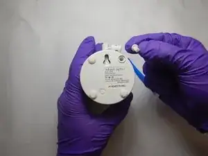
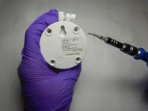
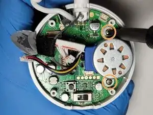
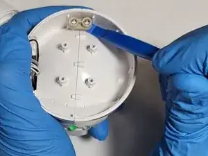
Position the camera with bottom facing toward you.
-
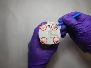
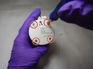
Using the plastic opening tool, remove all four rubber ends from the bottom of the camera.
-
-
-
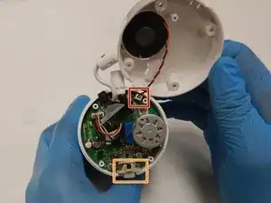
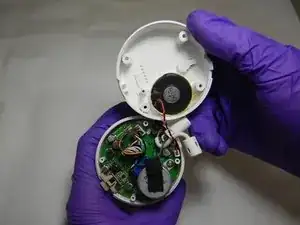
Disconnect the speaker wire and set the base plate to the side.
-
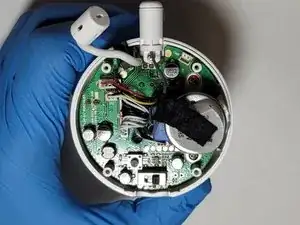
Remove the tan power selector.
-
-
-
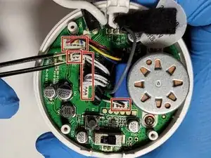
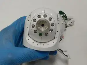
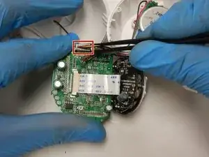
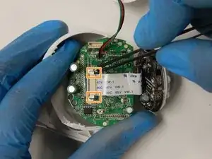
Using fine tip tweezers, disconnect the four electrical connectors on the board surface.
-
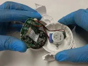
Using a Phillips #00 screwdriver, remove the two 5mm screws on either side of the motor.
-
Lift the motor from the board and set it to the side.
-
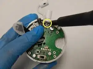
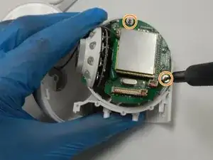
Using a Phillips #00 screwdriver, remove the 6mm screw from the antenna housing.
-
-
-
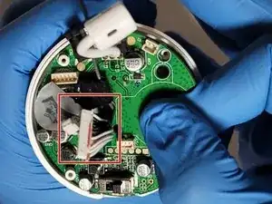
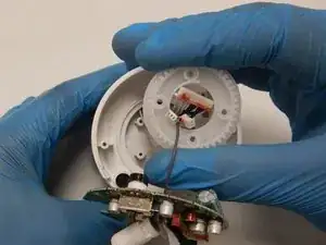
Lift the circuit board off the four locating pegs. Avoid lifting one side too much as it slides up the pegs to allow for smooth removal.
-
Feed the connectors through the slot in the center of the board.
-
-
-
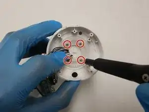
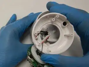
Using a Phillips #00 screwdriver, remove the four 6mm screws in the gear. Take note of the location of the tab on the gear for reassembly.
-
Feed the electrical connectors through the center hole of the gear and base housing.
-
-
-
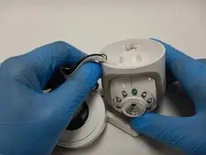
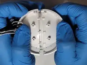
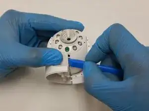
Gently but firmly split the camera housing. Use a plastic opening tool to assist in splitting apart the camera body if needed.
-
-
-
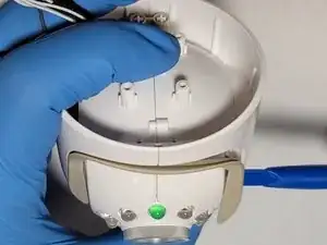
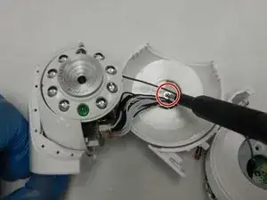
Using a Phillips #000 screwdriver, remove the 7.5mm screw holding the left camera leg to the camera body.
-
Feed the electrical connectors through the hole in the body of the leg.
-
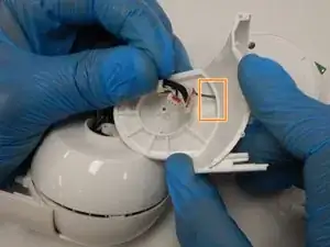
Feed the electrical connectors through the hole in the camera body.
-
-
-
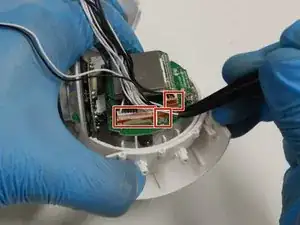
Using fine tip tweezers, disconnect the three electrical connectors from the motherboard.
-
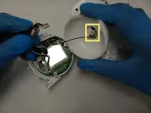
Using a Phillips #000 screwdriver, remove the two 5mm screws holding the camera motherboard in place.
-
Lift the camera motherboard off the locating pegs.
-
-
-
Using fine tip tweezers, disconnect the yaw motor electrical connector from the camera motherboard.
-
Carefully unlock the black ribbon cable locks to release the camera ribbon cable. Use the fine tip tweezers if necessary.
-
-
-
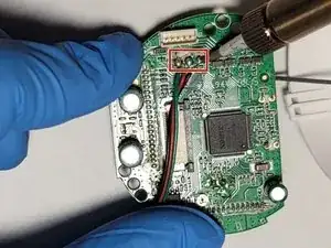
Using a soldering iron and desoldering braid, desolder the three limit switch wires from the camera motherboard.
-
Flip the board over.
-
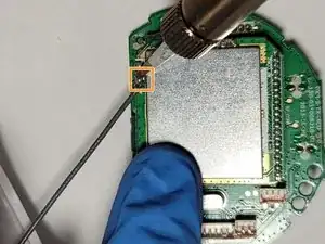
Using the soldering iron and desoldering braid, desolder the antenna from the camera motherboard.
-
To reassemble your device, follow these instructions in reverse order.
Un commento
We've had the microphone go in and out. Resetting doesn't work anymore, so I tore into it tonight (wish I would've seen this guide before, didn't think the connector glue would be as strong as it was). I did not make it past the first circuit board. What I couldn't figure out is where the microphone is.
I believe it's the enclosure with cord coming out with the antenna, soldered straight into the board. It could also be the temperature sensor. Thankfully pulling it apart and reassembling it got the microphone working again, but you can bet your bottom dollar it'll go out again.
Thanks for the guide, it was very helpful seeing what else is in there.