Introduzione
Strumenti
-
-
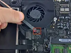
Rimuovere l'eventuale imbottitura morbida sulla parte superiore ed estrarre delicatamente il connettore dal rispettivo connettore femmina sulla scheda logica.
-
-
-
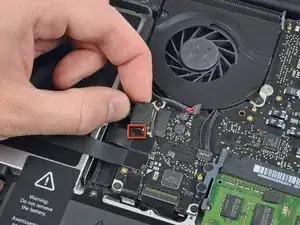
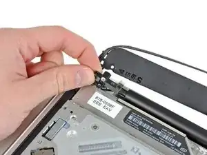
Tirare il connettore del cavo della fotocamera verso l'unità ottica per scollegarlo dalla scheda logica.
-
-
-
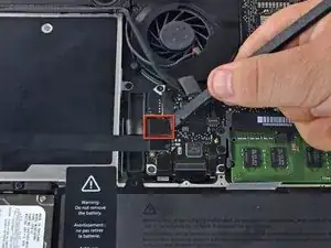
Utilizzare l'estremità piatta di un inseritore per rimuovere il connettore dell'unità ottica estraendolo dalla scheda logica.
-
-
-
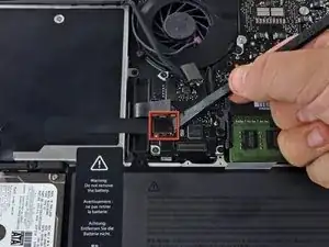
Utilizzare l'estremità piatta di un inseritore per rimuovere il connettore del disco rigido estraendolo dalla scheda logica.
-
-
-
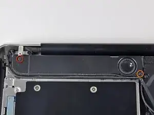
Rimuovere le viti seguenti, che fissano il subwoofer al case superiore:
-
Una vite con testa a croce da 3,8 mm
-
Una vite con testa a croce da 5 mm
-
-
-
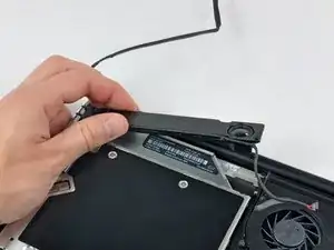
Rimuovere le due viti con testa a croce da 10 mm che fissano la staffa del cavo della fotocamera al case superiore.
-
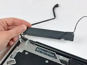
Sollevare la staffa del cavo della fotocamera fuori dal case superiore.
-
-
-
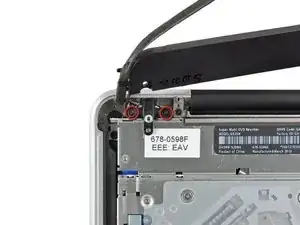
Rimuovere le tre viti con testa a croce da 2,5 mm che fissano l'unità ottica al case superiore.
-
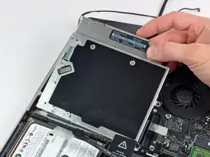
Sollevare l'unità ottica dal bordo destro ed estrarla dal computer.
-

Per riassemblare il dispositivo, seguire queste istruzioni in ordine inverso.

Un commento
Bonsoir. Le tuto est très clair, mais je voudrais savoir s’il est applicable sur la version 15” du MBP 10. Amicalement, Marc.
It is not necessary to remove the camera cable connector (step 5) or the camera cable connector (step 10). Simply push the camera cable gently aside to remove one of the three screws securing the optical drive (step 11). Gently wiggle the optical drive from under the camera cable connector and go to step 12. Less chance of ruining your motherboard!
tomhart -
Absolutely. Leave it alone, you don’t need to run the risks of removing this cable, I did the replacement fine without it
Steven Taylor -
It does indeed come out of the connector, but the picture makes it hard to see how; the connector it goes into sits on top of the board—however, I, too, ripped mine off the board trying to remove it; I only got it out of the clip after I tore it off. SIMPLY DONT; it's unnecessary. I plan to solder it back if one of my Robotics club friends lets me borrow a soldering iron.
Rachel -
Alors je déconseille très fortement de toucher ce connecteur, il est extrêmement fragile. De plus, cela n’a pas d’incidence sur la suite des opérations
Laskoni -
The author needs to go back through this guide and correct lots of order mistakes. The fan was removed in steps 3-5 yet it’s still being shown installed in steps 19-22.
plink53 -
The 4-pin push connector for the sub-woofer is near impossible to reconnect
It mates with a female connector that sits on top of 4 tiny solder points (it's held on by a spot of glue, I believe), and when applying ANY pressure to connect, the side clip(s) will snap off. Then the connector itself will become unglued. It would be simple enough to connect the 2 parts, then place a drop of glue on the logic board after positioning it above the solder points, but the female connector broke apart in my hand. So now screwed, with no way to connect sub/ R speaker without installing another logic board. Fan connector looks to be exactly the same
Peter Watkins -