Introduzione

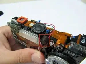
This will show a step-by-step process in replacing the microphone from your Kodak EasyShare LS743 Prior to beginning the guide, but sure to remove the batteries from the device.

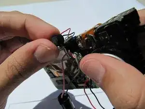
A warning for this guide: you will need to solder at the end of the guide to remove the microphone so if you don't know how or need a refresher, check out the How to Solder and Desolder Connections article.

  1. Ni6JlVp1aLMnPQuV
    • Using your fingernail, open the battery cover.

  2. NwiQNSaVPReuMs2k
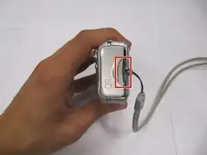
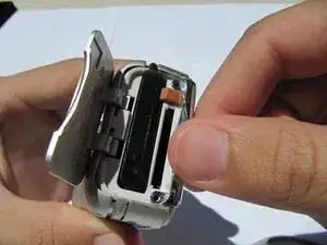
    • Slide the orange latch sideways to eject the battery.

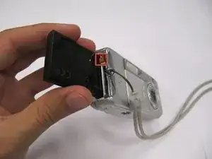
    • Remove the battery from the battery slot.

  3. R46BgCJdYk3RN55W
    R46BgCJdYk3RN55W
    C21EIbT4aZPVpFqx
    PLLROZREuZmMOCGV
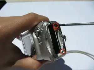
    • Using a Phillips #00 screwdriver, remove two 5.39 mm screws next to the battery slot.

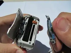
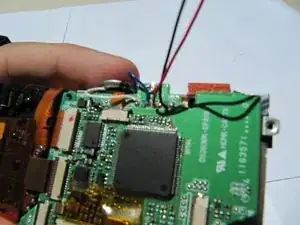
    • Remove the metal piece holding down the lanyard, then remove the lanyard.

  4. UPuqeIJGECEwkcWA
    UPuqeIJGECEwkcWA
    PIfdfT3cyoVNpljQ
    4eGPUrasjKqUKq5l
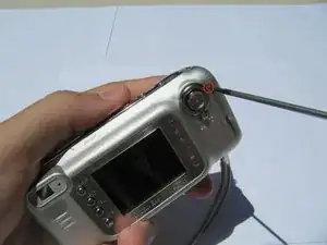
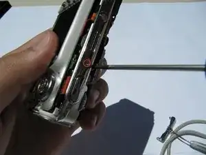
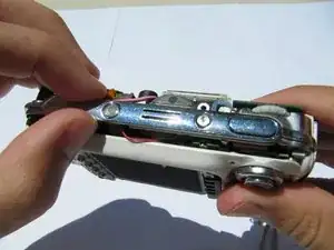
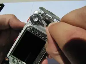
    • Using a Phillips #00 screwdriver, remove seven screws located on the outside case of the camera.

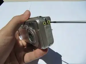
    • One 6.25 mm screw is located on the top right corner, right to the "OK" button.

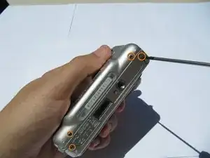
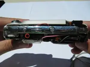
    • Four 4.45 mm screws are on the bottom of the camera.

    • Two 2.95 mm screws are on the left side of the camera, above the USB port.

  5. hxVUirV5j6kUioff
    hxVUirV5j6kUioff
    pp2qrHQYZBTFbBmB
    • Carefully remove the rear camera casing.

    • Carefully remove the front camera casing.

  6. pNKfQigsiYVSKXDZ
    pNKfQigsiYVSKXDZ
    XKWACNmV5TGd2gAr
    • Remove the top panel screw (1x 4.37mm).

  7. MHKpSKJkGnpejAdx
    MHKpSKJkGnpejAdx
    RwKFynswoRjSGhlO
    • Remove the top panel.

  8. 4ObOIipdtVDeMLWO
    4ObOIipdtVDeMLWO
    KbFHa5Fe2oZ2JGy2
    • Remove the back panel screws (1x 3.33mm, and 1x 3.40mm).

  9. uhFiTGpkSkJV1jVJ
    uhFiTGpkSkJV1jVJ
    CbmWoqZpypTvCNCT
    JHG1M3kjTZM2vOir
    • Separate the inner casing from the tripod mount.

  10. j5bFOBu6sSZxTQns
    j5bFOBu6sSZxTQns
    UgHNEW3u5jBZZ6Pn
    3MAdF3Q6oroYkNE6
    • Gently pull the orange tab out of the circuit board.

  11. ZCM1ovKHGwOOaEyZ
    ZCM1ovKHGwOOaEyZ
    yaT5xBHVnjKuary2
    • Carefully separate and flip over the LCD panel to expose the central circuit board.

  12. WZfw3Fj62RYhW3cM
    • Remove the (1x 3.33mm) screw from the menu button panel .

  13. rKee3eWJRYwr3WLI
    rKee3eWJRYwr3WLI
    Jkku4aj2dNjSLDQH
    • Pull the second orange tab from the circuit board and remove the buttons.

  14. 2WEZV1nP5jXqly1h
    2WEZV1nP5jXqly1h
    rBNDDjanwxXiLboY
    nHJgaerVXpDMI6CY
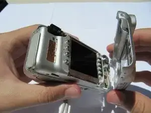
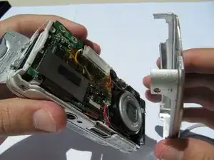
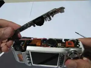
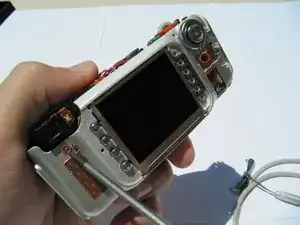
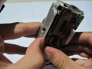
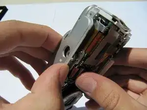
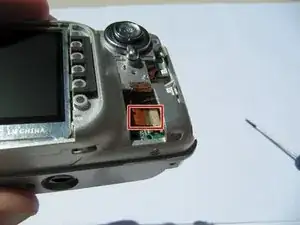
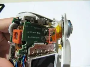
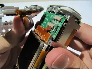
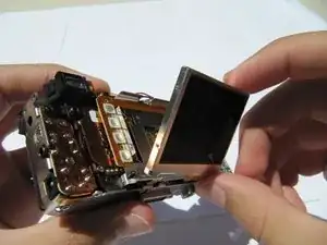
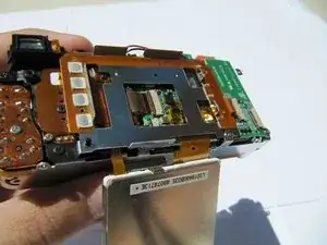
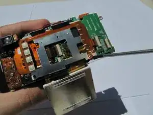
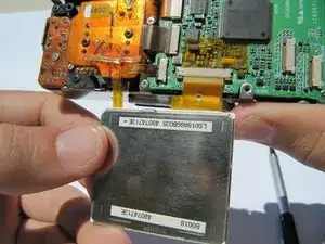
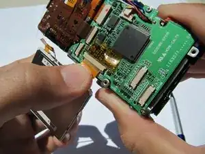
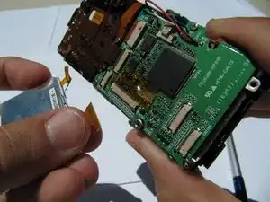
    • Flip up the LCD screen to reveal the two orange ribbon cables.

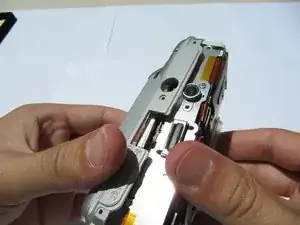
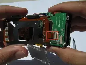
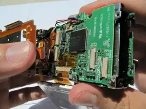
    • Disconnect the two ribbons cables from their sockets on the motherboard.

  15. KATibQrrxvrbkkPX
    • Locate the microphone on top of the camera.

  16. CPTly5ubRgsZAHH5
    • With an opening tool, pry the microphone away from the camera carefully.

  17. NWYIeJ5ZAGeAfkHL
    • Release the microphone from its pin and desolder.

Conclusione

To reassemble your device, follow these instructions in reverse order.

Odessa

Membro da: 24/06/10

55 Reputazione

0 commenti