Introduzione
The Lenovo Ideapad C340 or Flex 14 API has a problem with failing webcams. This happens especially when the notebook is used on the go a lot.
If your webcam suddenly fails and can be revived by flicking or tapping on the case near the webcam you probably have a loose connection and the webcam board must be reseated.
-
-
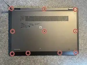
Remove the 10 Torx TX5 screws on the bottom case
-
With all screws removed pry off the cover with your fingernails or use a spudger.
-
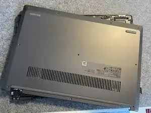
The cover should off quite easily.
-
-
-
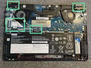
To remove the display assembly we have to take care of four areas
-
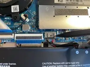
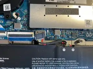
At first disconnect the battery before we move ahead. Use a spudger to carefully unplug the battery connector.
-
-
-
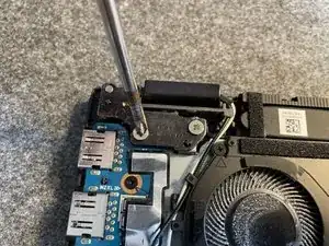
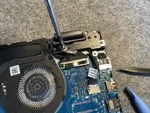
Unscrew the two screws of the right screen hinge
-
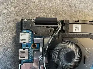
Unplug the display connector carefully using a spudger from the right side
-
-
-
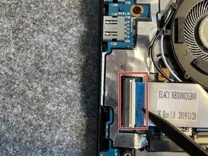
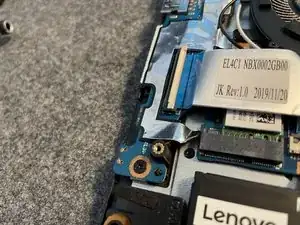
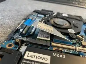
The extension board to the left is connected by a ribbon cable.
-
To unplug it lift up the white clip and carefully pull out the cable
-
-
-
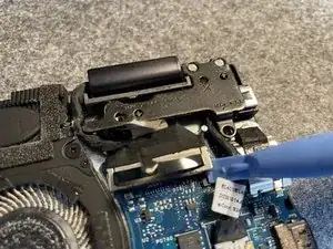
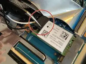
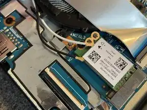
Depending on your model the two wifi connectors may be hidden under a soft rubber pad. Remove it with a pair of tweezers.
-
You can use the tweezers to lift up the wifi connectors from its plug. Be careful not to damage the cables in the process.
-
-
-
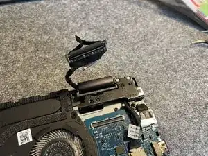
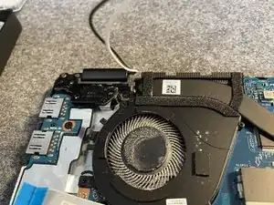
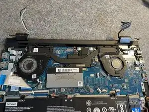
With all cables and connectors removed from the main board you can now gently lift up the hinges and separate display assembly from the rest.
-
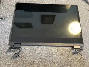
Now you have the display assembly only which gives you way easier access to further repairs.
-
-
-
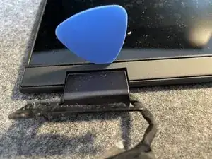
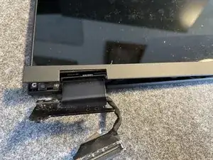
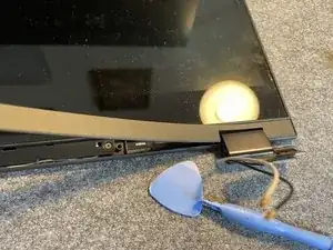
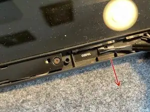
Pry off the flexible bottom cover of the display assembly.
-
You can use a spudger or a guitar pick to do so.
-
-
-
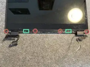
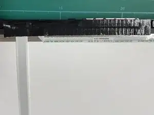
With the cover removed you will find 4 screws to be removed (red circles) as well as two strips of adhesive (green rectangles) you have to pull.
-
After unscrewing the four screws use a pair of tweezers to pull on the tabs of the rubber adhesive strips.
-
-
-
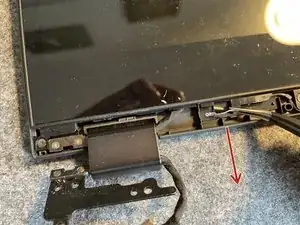
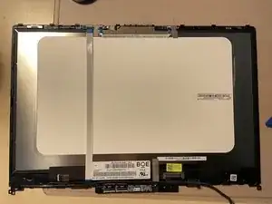
After you have removed the adhesive the display can be separated from its housing. Be careful with handling as the touchscreen is quite fragile
-
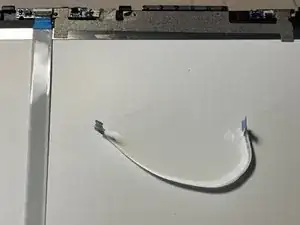
To proceed you have to unplug the ribbon cables like you did before on the mainboard.
-
Lift up the tabs and pull out the cables.
-
-
-
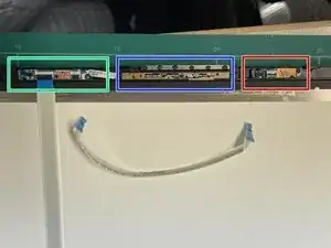
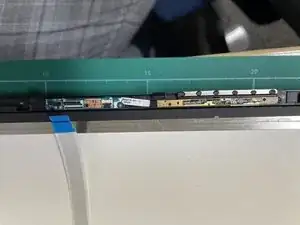
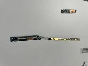
After removing the adhesive strip you can see that the webcam is divided into 3 logical units:
-
The first board (green rectangle) houses the indicator LED as well as the microphone. The second board (blue rectangle) is just the webcam with the part no. 01HW045. The smallest (red rectangle) seems to be a light sensor board
-
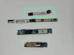
The boards are just glued into place and can easily be pryed out.
-
-
-
The connectors between the boards especially the ribbon cable (green rectangle) lose connection over time. This is why problems occur.
-
To fix just reseat all connectors carefully!
-
I used duct tape to create a stronger bond between the components.
-

To reassemble your device, follow these instructions in reverse order.
You might use double sided tape to glue the display back to its frame.