Introduzione

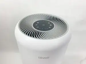
Your Levoit Core 300-RAC's power board distributes power safely from a wall outlet to the fan and control board. If your device's fan stops spinning or it simply won't power on, then your power board may have failed. This guide will walk you through replacing this critical part.

Before you begin the repair, take a look at the Levoit Core 300-RAC Troubleshooting page. Once you've determined it is the power board that needs to be replaced, make sure to power off the device and unplug it from the outlet before you begin.

  1. pfvPxZnQJHBKUEnb
    pfvPxZnQJHBKUEnb
    JyIEjELYcJISXCJw
    • Make sure your device is turned off and unplugged for safety.

    • Turn the Levoit Core 300-RAC over so the bottom is facing up.

  2. rsnpltPV4oSRwvdM
    rsnpltPV4oSRwvdM
    3jkKDE3u2EqbBIjm
    kHUIQprEMwGBOwnf
    • Turn the bottom cover counterclockwise and lift it off to remove it.

    • The cover does not "snap" on or off when turned.

  3. sZVi2pOMBwQHQNMk
    sZVi2pOMBwQHQNMk
    2RRBFtsKOKKYJ1yC
    wTQlGVaTguUNWVpC
    • Lift the filter straight up and out of the device.

  4. ELHZOC2CCGhgBShm
    ELHZOC2CCGhgBShm
    kNS4uW6dhPM2SVAv
    5Ub3YLZMb6C11RZP
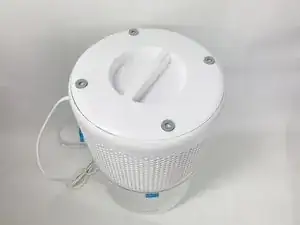
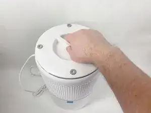
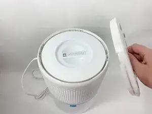
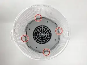
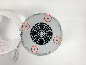
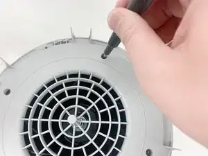
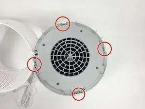
    • Use a Phillips #2 screwdriver to remove the four screws that secure the gray lid towards the base of the device.

    • Set the screws aside in a safe place.

  5. rIxJIVpHONLgYFIX
    rIxJIVpHONLgYFIX
    vvpcyYItPBEp143i
    4WJ2NjQwv3SiaUHa
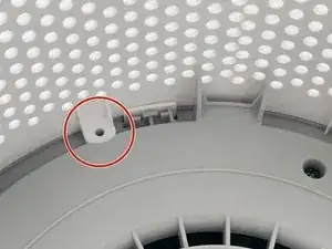
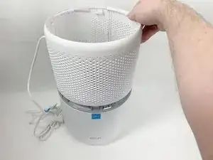
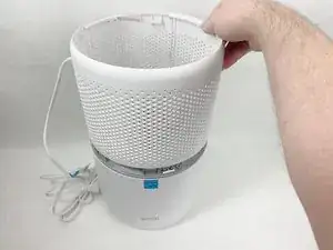
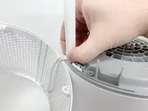
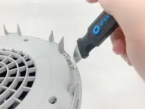
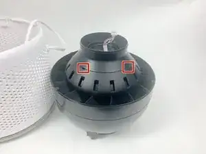
    • Use a metal spudger or Jimmy to gently pry between the four white tabs and the white housing to release the outer housing.

    • Gently pulling up on the outer housing can prevent the clips from resetting.

  6. G5pfkNidyKUAwC5d
    G5pfkNidyKUAwC5d
    nglbBkaPcVDME1Ae
    • Remove the white outer housing and set it to the side.

    • The power cord is fed through a hole in the side of this housing, so it has to sit right next to the device.

  7. VuiURstV6rE2GuIb
    VuiURstV6rE2GuIb
    iEEGOBDfkRuTnx4T
    PlHmZfUfjFop5DBM
    • Grab the cable channel by its base, squeeze, and pull up at the same time to remove it.

  8. uXZBFgDWHcPCB1AP
    uXZBFgDWHcPCB1AP
    IRMJtgahyS6VcZMh
    • Remove the four Phillips #2 screws securing the gray face plate.

    • Set the screws aside in a safe place.

  9. UrQm3lONTItSemef
    UrQm3lONTItSemef
    AdFVstbKLvcqisHL
    qYiUIbuFjBBrZgMv
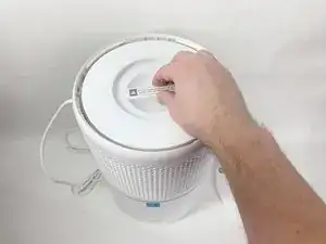
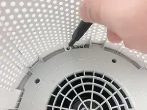
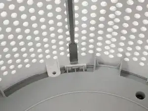
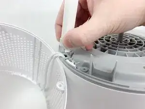
    • Insert a Jimmy or spudger between the white tab and the gray faceplate body to release the faceplate.

    • Lift it out.

  10. TC3MlOBQId1gXQJo
    • Turn your device over so it is upright again.

  11. V3eCoDVMFSsUIFnu
    V3eCoDVMFSsUIFnu
    6yOkUKFrcbFpCJl6
    AEIPchA12GxujaKy
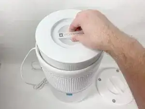
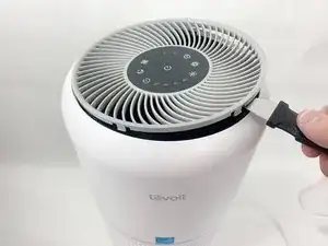
    • Insert the Jimmy between the gray grille cover and the top of the device.

    • Work your way around the grille cover with the Jimmy to release the clips holding it in place.

    • Take note of the placement of the clips, as they are keyed and need to go back in the exact way they came out.

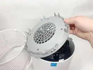
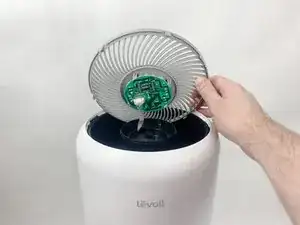
    • Remove the grille cover gently as it is connected by a ribbon cable.

    • Be careful not to put too much strain on the ribbon cable as it may break.

  12. xWB3LyrE1sBRqykN
    xWB3LyrE1sBRqykN
    SfllDsaEpnV5KN2X
    igvv3TRPaLJtMXOm
    • Squeeze the tab on the connector to release the bundled cable from the control board.

    • The connector should come out fairly easily, so do not force it. Pulling too hard could damage the connector.

  13. h3s1ymaGPxxkbrDy
    h3s1ymaGPxxkbrDy
    GACEUoPXPiTFEQoV
    hMeWphwNHZownO5H
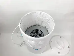
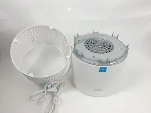
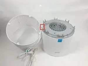
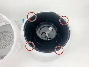
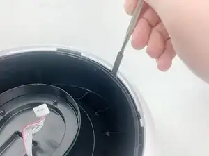
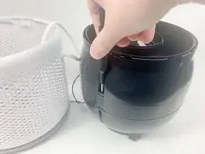
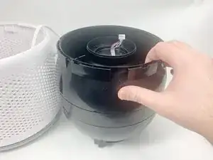
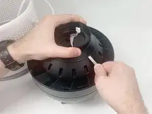
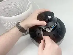
    • Insert a spudger or Jimmy into the four tabs to release them from holding the outer white housing to the inner black core.

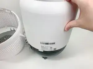
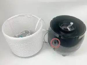
    • Remove the white outer housing.

  14. TdrqZuVgBn4jPh3k
    TdrqZuVgBn4jPh3k
    YjHQMNmRFpVmmYoL
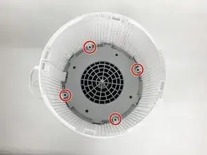
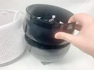
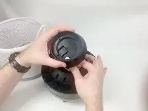
    • Use a Phillips #2 screwdriver to remove the three screws holding the top of the black center section to the middle section.

  15. qTQgwlFiBBwrnXyB
    qTQgwlFiBBwrnXyB
    yqX4LcjS6tdSysdF
    S4ursnGdKhoIdPdl
    • Lift and remove the upper portion of the black core.

  16. O14AxDV3jNVEFPio
    O14AxDV3jNVEFPio
    gCRnkUTbou6TMdLd
    MDJkh32qrNA4QakE
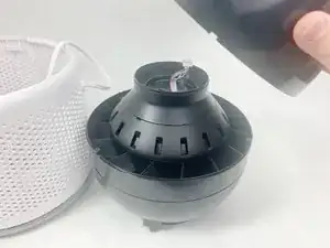
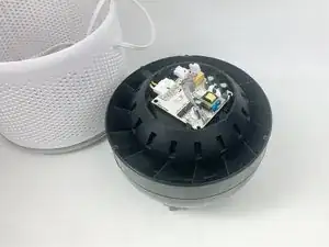
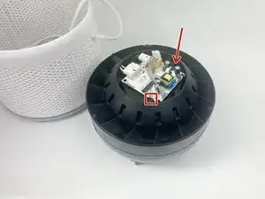
    • Insert a spudger into the slots around the seam to gently pry the upper part off of the assembly.

  17. EnG22X3A6MVsfDv5
    EnG22X3A6MVsfDv5
    GNDOCpNJQ6XGSYre
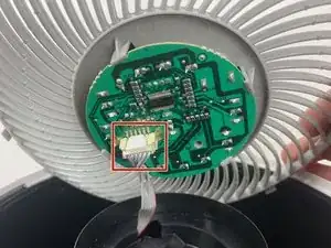
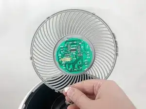
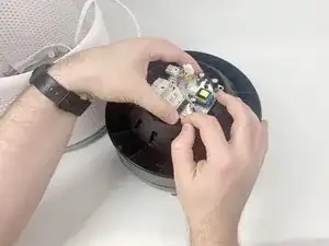
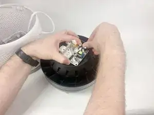
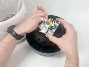
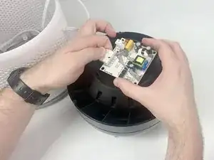
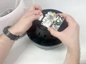
    • Feed the ribbon connector through the space in the top part of the assembly before removing it.

    • Carefully pass the connector through the hole so you do not damage it.

  18. jOWfAqLBsZVvOySB
    jOWfAqLBsZVvOySB
    V5UC2M3K65Un2tQK
    aWOdJs1v3AYZMwC1
    • Use your hands to pry apart the two tabs on opposite sides of the power board.

    • Use one hand to push on the tabs while gently lifting with your other hand to keep them from resetting.

    • There is a third tab that the board will slide out from under when the other two are released.

    • After releasing the two tabs shown, the power board will be free. Do not pull hard on the attached cables as that can damage them as well as other parts.

  19. rYWAgyQN2niXTyZc
    rYWAgyQN2niXTyZc
    A2JZlQUp2TZIWcWx
    UGkyG1H1BTtCJANG
    • Squeeze down on the clips holding the connectors in place to release the cables.

    • The power board is now completely removed.

Conclusione

To reassemble your device, follow these instructions in reverse order.

Ryan Medeiros

Membro da: 01/11/23

353 Reputazione

0 commenti