
Introduzione
This guide will show you how to replace the micro switches for the left and right mouse buttons of your Logitech G603 gaming mouse to resolve double-clicking issues.
This repair requires soldering so for those who are not experienced it may be a difficult repair. Please refer to the How to Solder and Desolder Connections for more information on soldering.
-
-
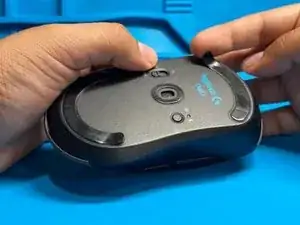
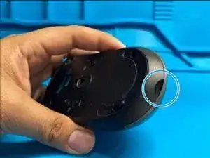
Flip the mouse onto its back.
-
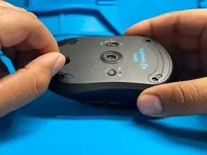
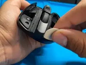
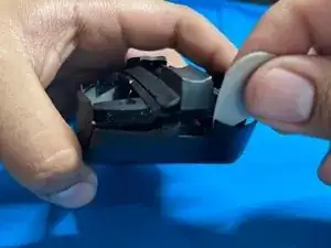
Peel back the pads on the top and bottom of the mouse to reveal the four screws.
-
-
-
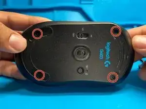
Remove the four screws with a small Philips screwdriver and set them aside.
-
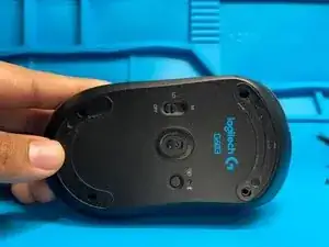
Remove the battery plate and batteries.
-
-
-
Start at the same location as the previous step, and use your thumb to carefully pry the base from the shell of the mouse.
-
-
-
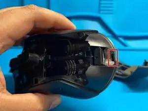
There will be two crevices that are attaching the base to the shell of the mouse.
-
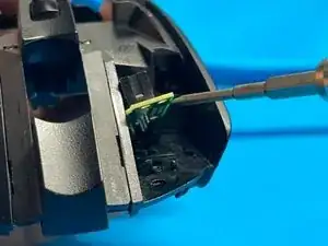
Using a spudger, gently and carefully pry along the dotted red line marked in the first photo until the shell and the base are separated.
-
-
-
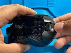
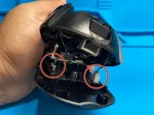
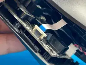
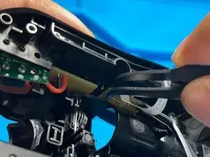
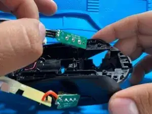
There will be two cables that need to be disconnected before completely separating the shell from the base.
-
-
-
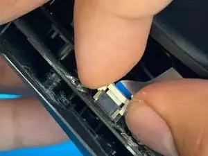
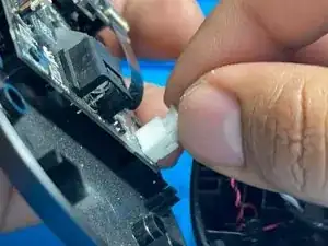
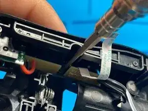
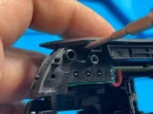
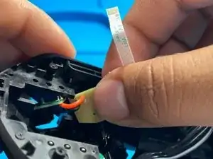
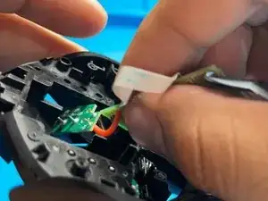
To remove the ribbon cable, use your thumb and index finger to pinch the latch upwards.
-
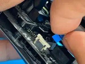
Once the latch has been released, pull the cable out of its slot.
-
-
-
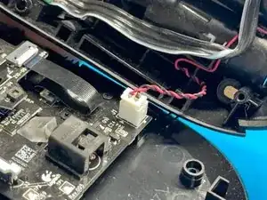
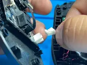
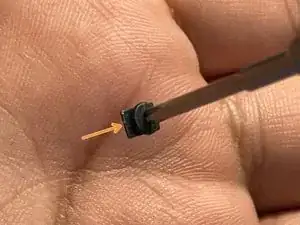
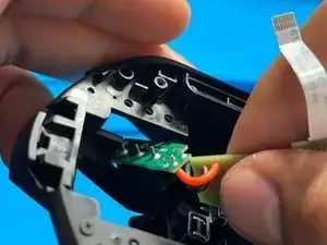
To remove the power cable, slowly and carefully wiggle the cable out of its socket either with your fingers, a spudger, or a flat head screwdriver.
-
-
-
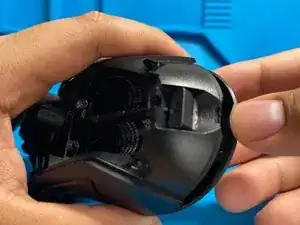
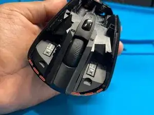
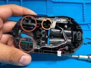
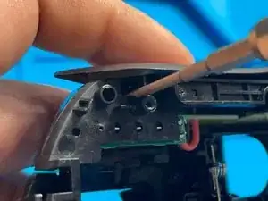
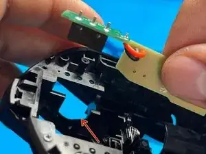
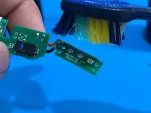
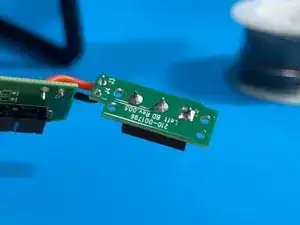
Here, you will be able to see the underside location of the switches that need to be replaced.
-
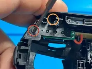
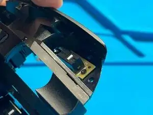
Here, you can see the location of the next step which will be to unfasten the side button circuit board.
-
-
-
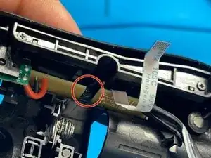
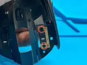
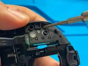
Locate the screw marked in the first photo. Remove it by using a Philips head screw driver and twisting in a counter-clockwise motion.
-
-
-
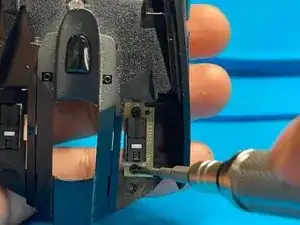
Use a screwdriver to remove the screw by twisting in a counter-clockwise motion.
-
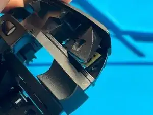
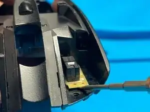
Using a flat head screwdriver, push the latch upwards and into hole from which it protrudes until the cover loosens.
-
-
-
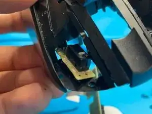
The switch board will be secured by two screws. Using a Philips head screwdriver, remove the two screws using a counter-clockwise motion.
-
-
-
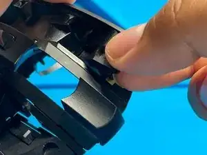
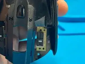
With the side board in hand, twist the board until there is enough room for the switch board to exit the gap located in the last photo.
-
-
-
Now that we have the first switch displaced, repeat steps 11-14 to displace the other.
-
Proceed to step 16 to remove the mouse switch from its hole
-
-
-
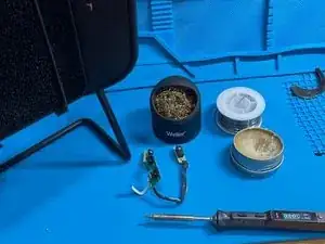
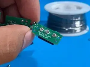
Now that the switches have been displaced, prepare your soldering equipment for the final steps.
-
-
-
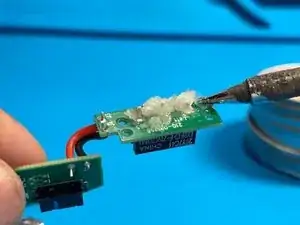
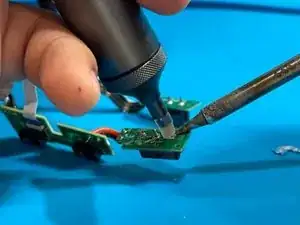
Once the residual soldering flux has been clean, begin soldering in the new switch into the board. Repeat steps 19 and 20 for the other switch.
-
To reassemble your device, follow these instructions in reverse order.