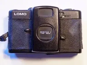
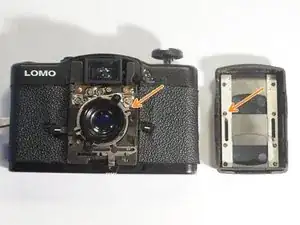
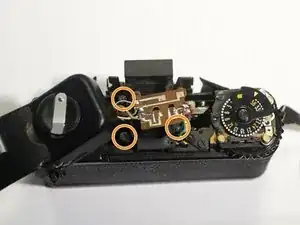
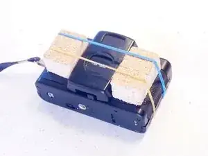
Introduzione
These analog Lomo cameras enjoying cult status for a growing community and are the cause for the "lomography" movement. Unfortunately, most of these cameras suffer from sticking shutter and apertures. Root cause are often oil residues or debris from the aging light seals.
Symptoms are either lots of underexposed or completely blank pictures.
This tutorial shows how to take apart and clean the parts from old oil residues.
-
-
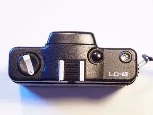
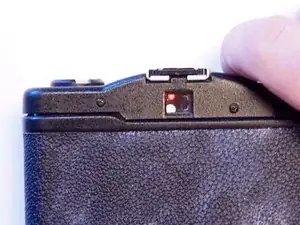
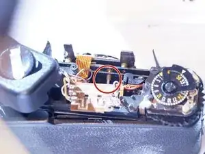
For a first check please connect a 4.5V powersupply instead of the batteries to the internal contacts. The left red LED in the viewfinder should light up when pressing the release button half way down. This makes sure that the electronic parts are working and a bad battery is not the problem.
-
The right LED will only light up in "A"-mode setting as a warning for low light (shutter button pressed half way). In this cause the exposure will be less than 1/30 sec which can lead to blurry images.
-
Cover up the light meter with a finger to simulate low light settings and check the left LED.
-
-
-
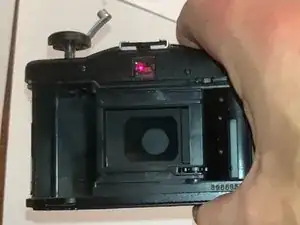
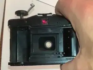
with open Back Cover, release the shutter and look through the Lens.
-
When using exposure settings "A" or 2.8 aperture, you should clearly see a wide open lens for a short period. If you don't see the lens, the shutters are stucked and needs to be cleaned.
-
-
-
Remove the 3 LR44 batteries.
-
Problems with shutters can also be caused by bad battery contacts. Check an clean the contacts with fine sand paper and apply contact spray.
-
-
-
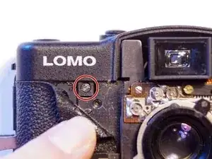
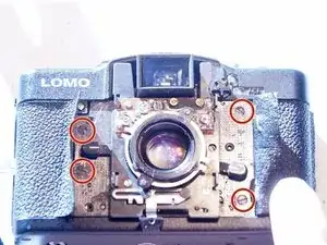
Remove the 4 screws (Phillips, 2.7mm) on the left and right side of the front cover. Lift the cover straight up. Sometimes it fits very tight. Just apply careful lifting force.
-
When assembling back together, move the lower lever at the camera body, which opens and closes the shutters, to the left ("open position"), and manually move the shutters in the front cover to open. Put them back together, moving the lever slightly until the parts gets a grip of each other and open and close together with the lever movement.
-
-
-
Using a scalpel or a sharp knife to remove the glue and loosen the leather in the grip area. Underneath the leather are hidden screws.
-
The one shown in the last picture needs to be removed in the next step.
-
Use gentle heat to soften the fake leather cover and expose 4 additional screws to be removed later. Carefully work the softened cover out from under the levers. I used a hot air station at 110C/230F
-
-
-
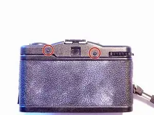
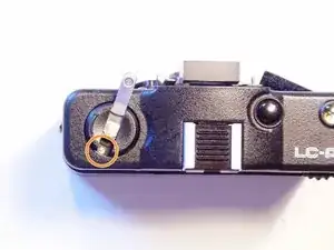
Remove the 2 black screws (Phillips, 3.8mm) on the back.
-
2 more screws (silver, flathead, 3.5mm) are hidden underneath the crank handle.
-
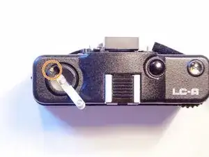
Remove the screw on the front side (see previous step): black, flathead, 4mm
-
-
-
This tip came from the great community, thanks to Parcival:
-
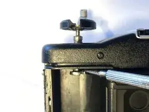
By blocking the Film axis with a screw driver, you can unscrew the film crank by turning the crank "counter clockwise" and take it completely off.
-
Note that the following steps still showing the top cover attached to the crank handle as I didn't know this trick before.
-
-
-
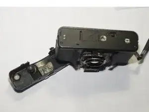
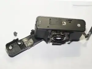
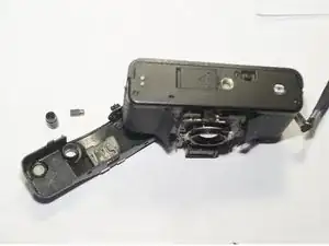
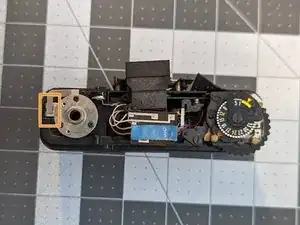
Turn the camera upside down to lift off the top cover. This will hold the release button in place.
-
Take out the release button (it consists of 2 parts put into each other). Make sure to put them together again in the correct way when assembling everything back together.
-
-
-
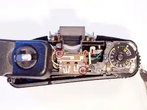
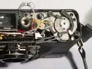
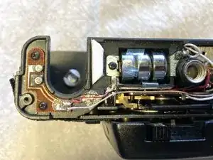
Remove the 2 black screws (Phillips, 3.6mm) from the printed circuit board for the LEDs.
-
Remove the 3 black screws (flathead, 5.5mm) holding the viewfinder in place.
-
Remove the viewfinder.
-
-
-
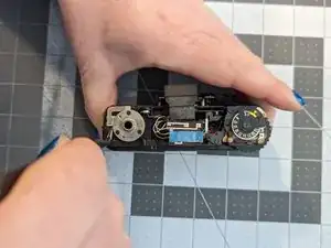
Using a tweezer to remove the litlle silver pin. Otherwise it will fall off later.
-
This pin transfers the distance settings from the lens to the viewfinder. Since Lomo enthusiasts never use the viewfinder, a loss is not too critical.
-
It will be critical if the pin falls into the camera and blocks mechanical part. Also make sure when assembling back, that there is no cable in the way which can block or short out things.
-
-
-
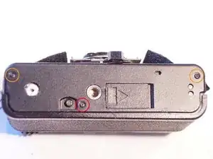
Remove the 2 black screws (Phillips, 3.6mm) at the left and right side of the bottom cover.
-
Remove the black center screw (Phillips, 7.1mm). Remove the bottom cover. Some rubber might fall off, which usually sits at the battery compartment door to keep pressure on it.
-
Remove the screw (Phillips, 3.7mm) from the battery compartment (the negative pole).
-
-
-
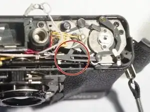
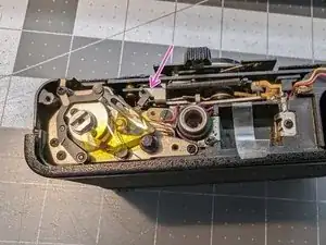
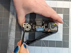
Lift the lever carefully off the pin, so that that both are not connected anymore to each other.
-
Sometimes these two parts become separated, causing problems winding the film.
-
Tape the lever to the body so that it does not flap about and get damaged. When re-assembling the front panel onto the body, make sure this lever is positioned here. On the other side you will be unable to wind the film.
-
-
-
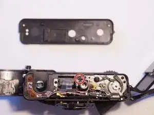
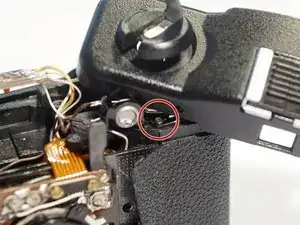
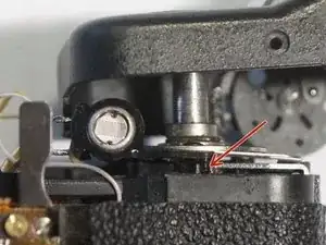
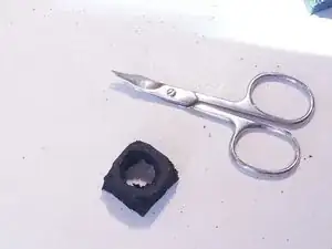
Remove the screw on the photoresistor. The part is hold in place by a little plastic pin. Very gentle try to get the part free.
-
-
-
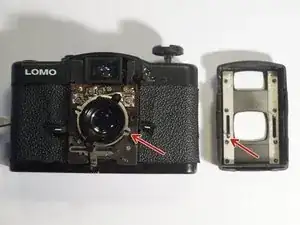
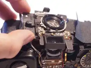
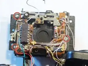
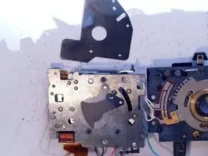
Remove the 4 screws (flathead, 4.1mm) holding the front assembly to the body.
-
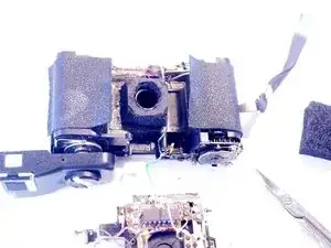
Carefully lift off the whole assembly, taking care not to bend, rip or quench cables.
-
One single cable keeps being attached to the body. Carefully move parts around. Be exceptionally careful with the two metal strips underneath the shutter. If these bend/break the camera will not work.
-
-
-
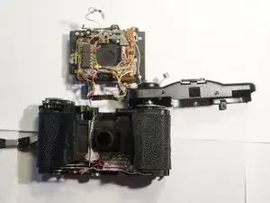
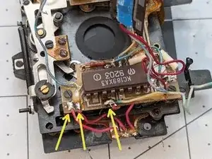
Remove flat PCB cable on either side of the assembly. For me the part on the lens side worked better.
-
Removing the 2 nuts, the bar and lift off the cable. Clean the contacts carefully before putting it back together.
-
If the ribbon cable is really glued down and you're worried about tearing it, you can de-solder these three wires to fold the assembly open with the ribbon cable.
-
-
-
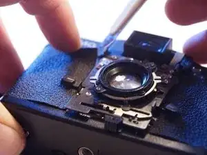
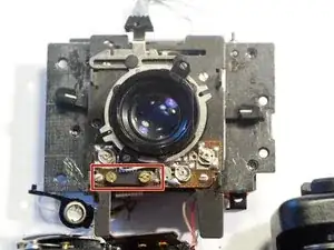
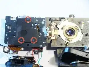
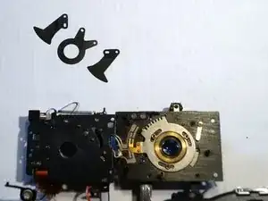
Remove the 3 silver screws (flathead, 3.2mm) holding the lens and the shutter assembly together.
-
Unfold both parts. Note they are still connected by 3 fine wires together.
-
Remove the 3 black screws (flathead, 2mm) to open up the shutter parts.
-
-
-
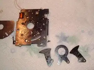
Shutter/Aperture consists of 3 fragile pieces and 3 tiny washers. Make notes to put them back in the correct order and orientation (see 2nd picture). The washers keep the shutter pieces level.
-
Last picture from another camera showing how bad the oil residue can be. Probably due to usage of wrong oil. Clean and dry everything with IsoPropylAlcohol and a microfibre cloth. These shutter parts DO NOT need any grease or oil at all.
-
If you want to grease other mechanical parts, make sure to use finest, resin-free oil (no WD40 or similar).
-
-
-
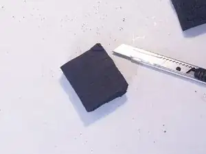
Take some high quality foam rubber and cut out a light seal for the body. In most cameras the original seal has turned into dust.
-
Residues from the old light seal can be the source of sticky shutters. Remove old residues carefully.
-
-
-
Putting back everything in reverse order.
-
Adding a little patch of foam rubber at the battery compartment causes a better fit of the battery lid.
-
Using double sided sticky tape to glue the leather back onto the body after putting everything back togeter.
-
Enjoy your new working Lomo camera!
-
-
-
If the film door shuts without the winder crank, you will need to lift up on this metal piece.
-
Carefully wiggle your tweezers or a fine screwdriver underneath.
-
Then lever it up and the film door should pop open.
-
Note: This is a lot easier with the circular top plate and spring removed, but this part is a real pain to re-assemble due to a tiny washer.
-
Arbeite die Schritte in umgekehrter Reihenfolge ab, um dein Gerät wieder zusammenzubauen.

2 commenti
Very nice guide, and timely. Just found my old Lomo and it has this problem! Question on the foam around the lens, how thick should that be?
Parcival -
I made mine about 5mm thick, but should be no problem if this is thicker. It should seal the gap and stay in place when working and assembling parts. Just stumbled across light seal foam from EDPM on different shopping sites, I may test that next time I take my camera apart.