
Introduzione
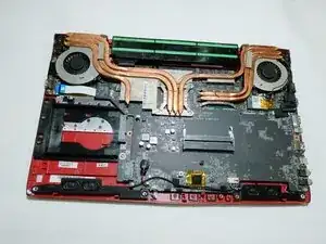
Given that your MSI GP62MVR 6RF Leopard Pro is charged, the most attributable reason for your laptop failing to turn on is some motherboard component failure. Unless you can pinpoint the exact place of malfunction, an entire replacement of the motherboard will most likely be the solution to a total failure of your MSI GP62MVR 6RF Leopard Pro. This process is not as hard as it may seem. No special skills are required. You will need a Philips #0 screwdriver, a jimmy tool, a prying tool, and a pair of latex gloves. Although the latex gloves are not required, we recommend them to avert the hazard of electrical shock or the leaving of residue on sensitive electrical components on the motherboard.
Strumenti
-
-
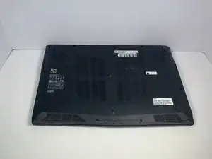
Place the laptop upside down.
-
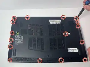
Remove the sixteen 5.5 mm screws with a Phillips #0 screwdriver.
-
-
-
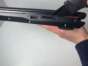
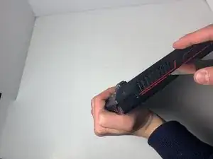
Use the Jimmy tool to evenly pry loose the bottom cover.
-
Ensure that all sides are detached from the plastic hinging before attempting to remove the bottom cover.
-
-
-
Using a Phillips #0 Screwdriver, remove the single 5.5 mm screw fastening the battery to the body of the computer.
-
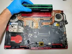
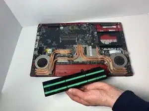
Remove the battery from the device.
-
-
-
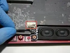
On the front panel near the right speaker, there is a connection from the motherboard to the speakers.
-
Detach the white and black wiring from the clip.
-
-
-
Peel back the electrical tape holding the speaker wire in place.
-
Remove the speakers from the front panel, pulling upward.
-
-
-
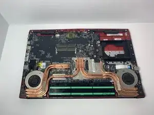
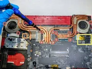
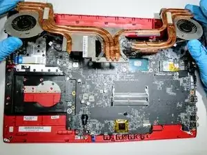
Using a Phillips #0 screwdriver, remove twelve 4.5 mm screws fastening the heat sink to the motherboard.
-
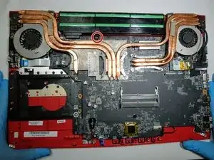
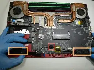
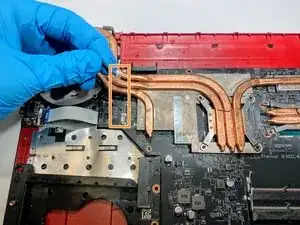
Unclip the red, blue, and black intertwined wire gently from the left side of the motherboard.
-
Detach the black and red wire from the right side of the motherboard, as well as peel away the black tape connecting the large black wire to the motherboard.
-
-
-
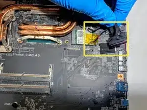
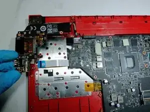
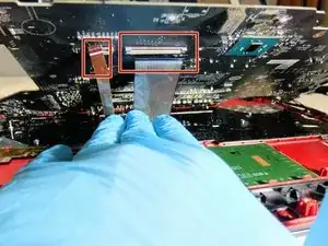
At the middle-top right of the motherboard, there is a ribbon wire connection to the USB port.
-
Detach the white and blue motherboard ribbon from the USB port.
-
-
-
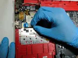
At the top right of the motherboard, there is a wired connection to the charging port.
-
Disconnect the grey charger wire from its clip on the motherboard.
-
-
-
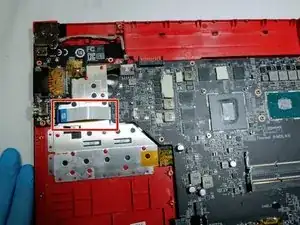
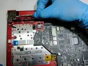
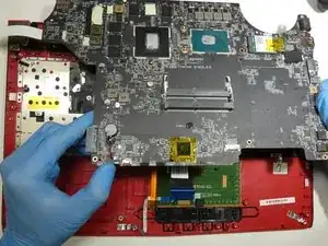
The final two connections are located one the underside of the motherboard.
-
Detach the small orange and bid grey ribbons from under the motherboard, by lifting the motherboard gently from the front.
-
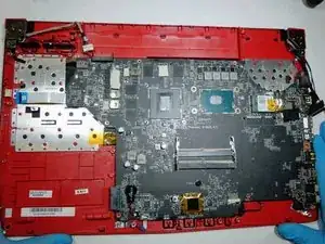
To reassemble your device, follow these instructions in reverse order.