
Introduzione
Use this guide to replace the I/O bezel and its integrated antennas. Replacing the I/O bezel will also give you a new power button.
-
-
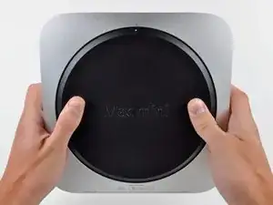
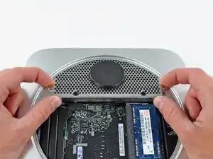
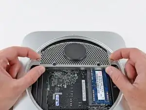
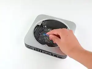
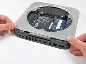
Place your thumbs in the depressions cut into the bottom cover.
-
Rotate the bottom cover counter-clockwise until the white dot painted on the bottom cover is aligned with the ring inscribed on the outer case.
-
-
-
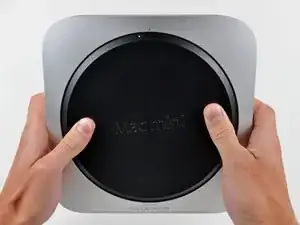
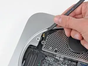
Tilt the mini enough to allow the bottom cover to fall away from the outer case.
-
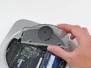
Remove the bottom cover and set it aside.
-
-
-
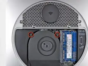
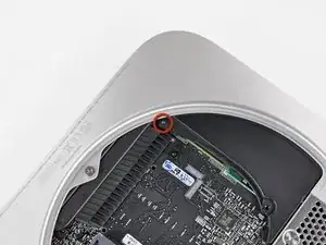
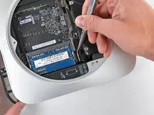
Remove the two 11.3 mm T6 Torx screws securing the fan to the logic board near the antenna plate.
-
-
-
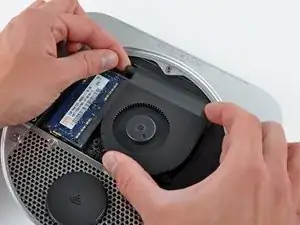
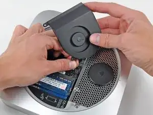
Lift the fan out of the mini for enough clearance to access its connector.
-
Carefully pull the fan cables upward to lift the fan connector up out of its socket on the logic board.
-
Remove the fan.
-
-
-
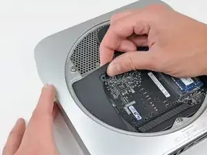
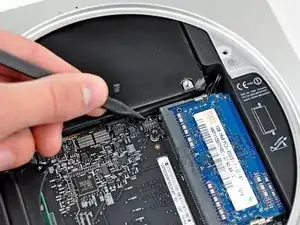
Lift the cowling from the end nearest the antenna plate.
-
Rotate the cowling away from the outer case and remove it from the mini.
-
-
-
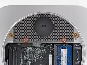
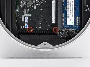
Remove the following screws securing the antenna plate to the mini:
-
Two 6.6 mm T8 or T9 Torx screws
-
Two 5.0 mm T8 Torx or 2.0 mm Hex screws (either will work)
-
-
-
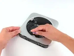
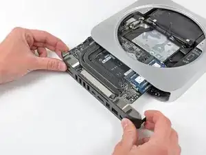
Slightly lift the antenna plate from the end closest to the RAM.
-
Carefully pull the antenna plate straight away from the circular rim of the outer case.
-
-
-
Use the tip of a spudger to carefully pry the antenna connector up off the AirPort/Bluetooth board.
-
-
-
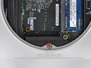
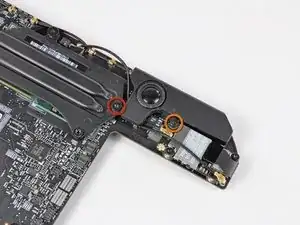
Remove the following three screws:
-
One 5.0 mm T8 Torx or 2.0 mm Hex screw (either will work)
-
One 16.2 mm T6 Torx screw
-
One 26 mm T6 Torx standoff
-
-
-
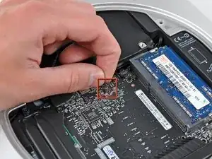
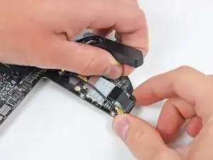
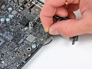
Carefully pull the wires for both hard drive thermal sensors upward to lift their connectors up and out of the sockets on the logic board.
-
-
-
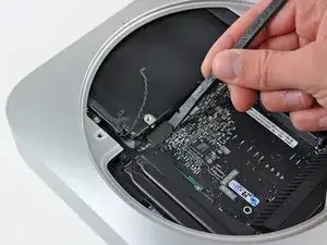
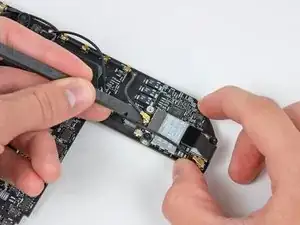
Use the flat end of a spudger to pry both the hard drive and optical drive connectors up out of their sockets on the logic board.
-
-
-
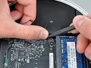
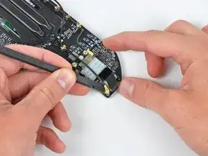
To disconnect the optical drive thermal sensor, pinch its cables between your thumb and a spudger and pry the spudger upward to lift the connector up and out of its socket on the logic board.
-
-
-
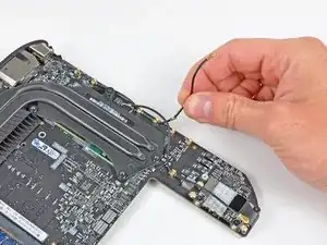
Use the tip of a spudger to lift the IR sensor connector up and out of its socket on the logic board.
-
-
-
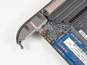
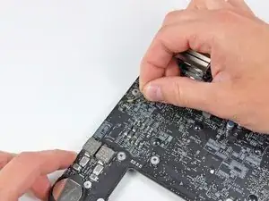
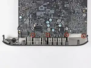
Insert a Mac mini Logic Board Removal Tool into the two holes highlighted in red. Be sure it makes contact with the outer case below the logic board before proceeding.
-
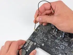
Carefully pull the tool toward the I/O board. The logic board and I/O board assembly should slightly slide out of the outer case.
-
Cease prying when the I/O board is visibly separated from the outer case. Remove the Mac mini Logic Board Removal tool.
-
-
-
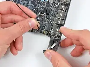
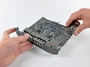
Simultaneously push the two plastic clips on the far left and right sides of the I/O board toward the middle of the I/O board and pull the I/O board away from the outer case.
-
-
-
Pull the I/O board/logic board assembly out of the outer case enough to access the power connector.
-
Use a pair of tweezers to disconnect the power cable from the logic board.
-
-
-
Carefully slide the logic board assembly out of the mini, minding any cables that may get caught.
-
-
-
Remove the following two screws securing the speaker to the logic board assembly:
-
One 4.2 mm T6 Torx
-
One 3.7 mm T6 Torx
-
-
-
Carefully lift the speaker wires upward to lift the speaker connector up and out of its socket on the logic board.
-
-
-
Use the flat end of a spudger to pry the antenna connectors up off the AirPort/Bluetooth board.
-
-
-
De-route both antenna cables from the clips securing them to the top side of the logic board.
-
-
-
Remove the single 2.6 mm T6 Torx screw securing the I/O bezel to the logic board near the RAM.
-
-
-
Carefully un-clip the antenna from the logic board near the PRAM battery.
-
Gently de-route the antenna cable through the hole in the logic board.
-
De-route the antenna cable from the clips on the logic board near the I/O bezel.
-
-
-
Lift the power button cables upward to gently pull the power button cable up and out of its connector on the logic board.
-


To reassemble your device, follow these instructions in reverse order.
