Introduzione

Use this guide to remove the heat sink. Before reinstalling the heat sink, be sure to apply a new layer of thermal paste.

  1. 3bTejPotVlS4MkaI
    • Before proceeding, power off the device, close the lid and lay it on a soft surface top-side down.

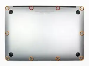
    • Remove the following ten screws:

    • Two 9 mm 5-point Pentalobe screws

    • Eight 2.6 mm 5-point Pentalobe screws

    • The special screwdriver needed to remove the eight 5-point Pentalobe screws can be found here.

  2. WwI3rtRnhTEHj54C
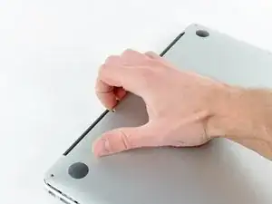
    • Wedge your fingers between the display and the lower case and pull upward to pop the lower case off the Air.

    • Remove the lower case and set it aside.

  3. CtyAZgC3dvRCcjK1
    • For precautionary purposes, we advise that you disconnect the battery connector from the logic board to avoid any electrical discharge. This step is optional and is not required.

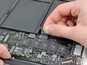
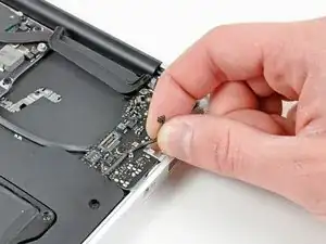
    • Grab the clear plastic pull tab attached to the battery connector and pull it toward the front edge of the Air to disconnect the battery from the logic board.

    • Do not lift upward on the connector as you disconnect it.

  4. kpxaSggiRGXdYbjE
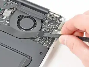
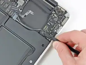
    • Use the flat end of a spudger to pry the I/O board cable connector upward out of its socket on the I/O board.

    Die nachfolgenden Schritte sind nicht erforderlich. Bitte bei Schritt 11 weitermachen.

    Volker -

    Es ist nicht erforderlich, IO-Board, Akku und Logic-Board auszubauen. Es genügt, die Antennen- das Kamera- und das Displaykabel zu entfernen und die Scharniere abzumontieren. Die Kabel können leicht an den vorhandenen Komponenten vorbeigezogen werden.

    Volker -

  5. JoLRPuB2CEeYNKPR
    JoLRPuB2CEeYNKPR
    PcuVr1BCTqIGgwtt
    • The following connector has an especially deep socket. Use care when disconnecting it.

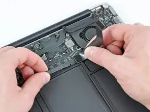
    • Carefully peel the I/O board cable from the top of the fan.

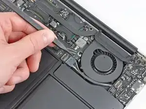
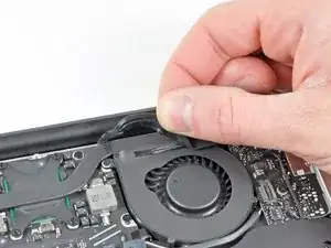
    • While gently pulling the I/O board cable upward near its connection to the logic board, use the tip of a spudger to pry upward on alternating sides of the connector to help "walk" it out of its socket.

    • Remove the I/O board cable.

  6. UZlXrZGTJBlUa2jW
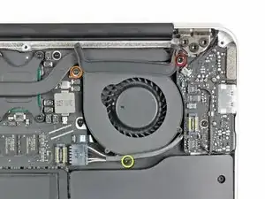
    • Use the tip of a spudger to carefully flip up the retaining flap on the fan cable ZIF socket.

    • Be sure you are prying up on the hinged retaining flap, not the socket itself.

  7. dXwOKmddcEdji1Xs
    • Peel the rubber gasket off the adhesive on the top of the fan.

  8. VBpNeyKDnHWwOWP1
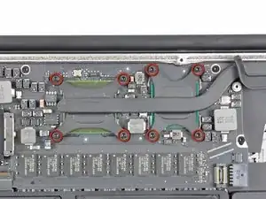
    • Remove the following three screws securing the fan to the upper case:

    • One 3.6 mm T5 Torx screw

    • One 2.7 mm T5 Torx screw

    • One 3.6 mm T5 Torx screw with a short head

  9. VCwgGU4PCVpaaYve
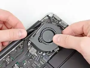
    • Lift the fan out of the upper case and carefully pull the fan ribbon cable out of its socket as you remove it from the Air.

  10. XCbFcg2VJhKEO6HT
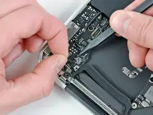
    • Disconnect the I/O board by pulling the power cable away from its socket on the logic board.

    • Pull the cable parallel to the face of the logic board toward the right edge of the Air.

    When assemble, Step9 fan connector first

    taizoy0725 -

  11. MQTvg4NSOMar4C3A
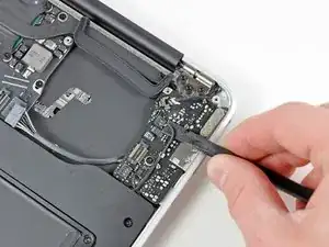
    • Pull the camera cable parallel to the face of the I/O board toward the corner of the Air to disconnect it from its socket, using the tip of a spudger to help push the connector out of its socket.

    • Do not lift upward on this cable as you disconnect it, as its socket may break off the logic board.

    Die nachfolgenden Schritte sind nicht erforderlich. Einfach bei Schritt 20 weitermachen.

    Volker -

  12. pXno2e11SBEnVUyw
    pXno2e11SBEnVUyw
    Nh432KJ1kGSJCsUx
    • Use the flat end of a spudger to pry the left speaker cable connector up and out of its socket on the I/O board.

    • Pry up from beneath the wires.

    • De-route the left speaker cable from its retainer on the I/O board.

  13. OrTXcFRwog2As2l2
    • Use the flat end of a spudger to pry the microphone cable connector up and out of its socket on the I/O board.

    • Pry up from beneath the wires.

  14. QDtqaHJCJ4c4Hr2q
    • Remove the single 3.6 mm T5 Torx screw securing the I/O board to the upper case.

    When inserting new board, make sure the headphones jack socket rim is registered properly with the case hole before tightening T5 screw.

    sutherlandralph -

  15. 23KDPd4D1muBh3tI
    • Carefully lift the I/O board from its edge nearest the logic board and remove it from the upper case.

  16. cMh3GC5ptyiimyXO
    • Remove the eight 2.5 mm T5 Torx screws securing the heat sink to the logic board.

  17. DYTCBTRMyGAI6KIj
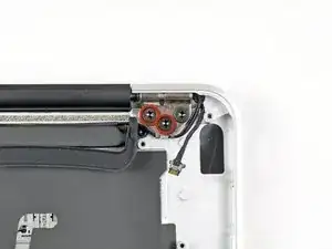
    • Remove the two 4.9 mm T8 Torx screw securing the antenna cable retainer on the left display hinge to the upper case.

  18. nyUfSGyLVeMeiXrE
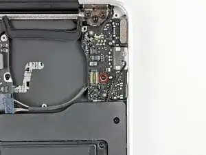
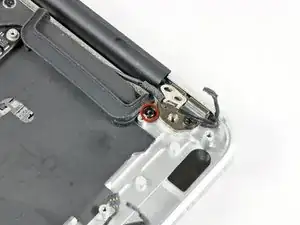
    • Push the antenna cable retainer out of the way and remove the 3 mm T5 Torx screw securing the end of the heat sink to the upper case.

  19. ZkCOqOZMrVgORoq4
    ZkCOqOZMrVgORoq4
    dLeSBFGGRaFTMCPK
    • If the heat sink seems to be stuck to the logic board after removing all eight screws, use a spudger to carefully separate the heat sink from the faces of the CPU and GPU.

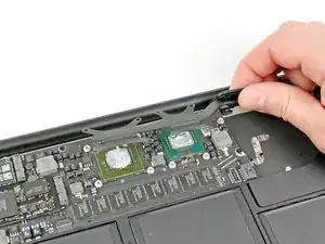
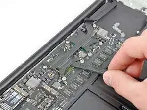
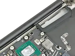
    • Remove the heat sink from the logic board.

    • When reinstalling the heat sink, be sure to apply a new layer of thermal paste. If you have never applied thermal paste before, we have a guide that makes it easy.

  20. IeCDCTPUQvRPWYmL
    IeCDCTPUQvRPWYmL
    gTeuKZwfDRXFXPHY
    • These shots show how the rubber fan gasket should be installed during reassembly. Be sure not to install the gasket underneath the ear where the end of the heatsink is screwed down to the upper case.

    • Additionally, be sure the small post molded into the rubber gasket mates with the hole cut into the upper right corner of the logic board.

Conclusione

To reassemble your device, follow these instructions in reverse order.

Andrew Bookholt

585555 Reputazione

0 commenti