Introduzione

Use this guide to replace the solid state drive tray.

  1. XxSVygoKg3BQZUeK
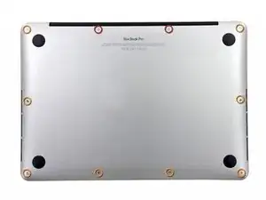
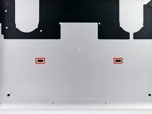
    • Remove the following ten screws securing the lower case to the upper case:

    • Two 2.3 mm P5 Pentalobe screws

    • Eight 3.0 mm P5 Pentalobe screws

    • Throughout this repair, keep track of each screw and make sure it goes back exactly where it came from to avoid damaging your device.

  2. TZjAGsfhlId3q36t
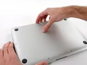
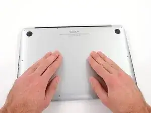
    • Wedge your fingers between the upper case and the lower case.

    • Gently pull the lower case away from the upper case.

    • Remove the lower case and set it aside.

  3. SLwb4KCgFZKfLR2B
    SLwb4KCgFZKfLR2B
    3eGiEP35uex15jKd
    muPIBpQokGnUUXJP
    • During reassembly, gently push down the center of the lower case to reattach the two plastic clips.

    • The lower case is connected to the upper case at the center, with two plastic clips.

  4. oh6QmDClHy3Es55f
    • Remove the plastic cover adhered to the battery contact board.

  5. AvPUsRLbmXLZWSlb
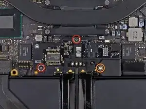
    • Remove the following screws securing the battery connector board to the logic board:

    • Two 2.8 mm T6 Torx screws

    • One 7.0 mm T6 Torx shouldered screw

  6. eYeaxKQXRIv43WNX
    eYeaxKQXRIv43WNX
    INge1d6OYG2XdrMr
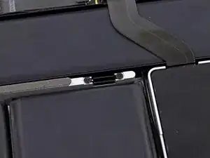
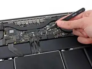
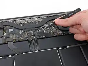
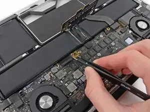
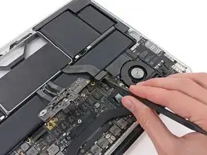
    • Use tweezers to remove the small plastic cover located near the bottom right of the battery connector board.

  7. 3h3p5bF5gSsxU3H1
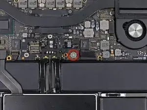
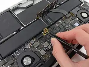
    • Remove the wide head 6.4 mm T6 Torx screw securing the battery connector to the logic board assembly.

  8. KnflDJ6YcW61sb3S
    KnflDJ6YcW61sb3S
    Y3LPyukbnPaH2Qua
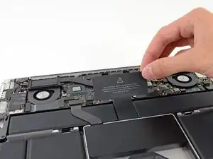
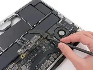
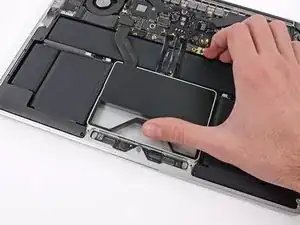
    • Carefully lift the battery connector board up off the logic board.

    • It is recommended to bend the battery cables just slightly, to keep the board suspended up above the logic board and out of the way.

    • Do not fold the board completely over, or crease the cables, as this may damage the battery.

  9. wBB3HYE4h4RPE1gv
    wBB3HYE4h4RPE1gv
    oUwSuUJp4RWM4RSK
    • Grasp the Interposer with tweezers.

    • An interposer is the name for an interface that links one electrical connection to another. In this repair, it is the board connecting the battery to logic board.

    • Lift the Interposer off the logic board and remove it.

    • Removing this board will ensure that the battery remains disconnected throughout your repair, preventing your computer from accidentally powering on. It's also a good idea to take it out so it doesn't fall out unexpectedly.

  10. VjHPHC5XpI5lyEU2
    VjHPHC5XpI5lyEU2
    YLwqCMl14OpjFG6c
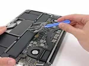
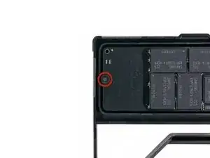
    • Use the flat end of a spudger to pry the SSD cable connector up from its socket on the logic board.

  11. MUtvMWqeoeVRNXgU
    MUtvMWqeoeVRNXgU
    1MmiJVae2W62kGCd
    i6Vtm3oAeyeI34BK
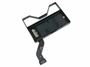
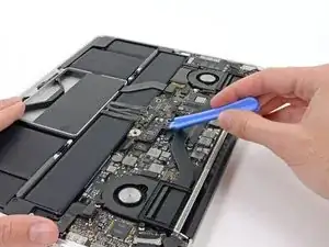
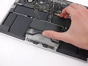
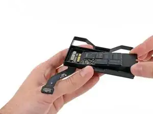
    • Use your thumb or finger to bend the plastic spring bar on the SSD tray, freeing the two clips at the front side of the device.

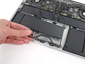
    • While holding the spring bar depressed, tilt the SSD assembly up out of its cavity.

  12. XNPcBcAJFlwmMOW3
    • Remove the SSD assembly from the upper case.

  13. bnHSZLCMEdST1Uh1
    • Remove the single 2.9 mm T5 Torx screw securing the SSD to the SSD tray.

  14. mJmLhQUw3uMNrOkr
    mJmLhQUw3uMNrOkr
    5J5PTAGiQZlhAwOl
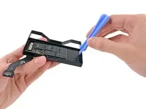
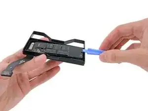
    • Insert the edge of plastic opening tool between the SSD and the SSD tray, opposite to the socket side of SSD tray.

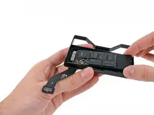
    • Pry the side of the SSD opposite the SSD tray socket out of the SSD tray.

    • Only lift the SSD up far enough to grab the sides of it with your fingers. Lifting it any more may damage the card or socket.

  15. FXSmWRFFRG1BBvja
    FXSmWRFFRG1BBvja
    IdDkqa4yg2sTXgWB
    • Carefully pull the SSD straight out of its socket on the SSD tray.

  16. HE4NYdWMelWhSKUa
    • SSD tray remains.

Conclusione

To reassemble your device, follow these instructions in reverse order.

Sam Goldheart

Membro da: 19/10/12

465140 Reputazione

0 commenti