Introduzione
Display connection issues? Use this guide to replace a faulty display data cable rather than replacing the entire display.
Ricambi
-
-
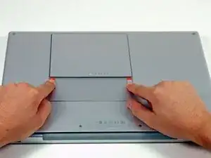
Use your fingers to push both battery release tabs away from the battery, and lift the battery out of the computer.
-
-
-
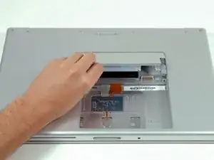
Lift the memory door up enough to get a grip on it, and slide it toward you, pulling it away from the casing.
-
-
-
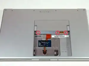
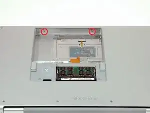
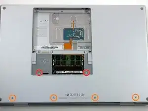
Remove the following 6 screws:
-
Two 10 mm T6 Torx screws on either side of the RAM slot.
-
Four 14.5 mm Phillips screws along the hinge.
-
-
-
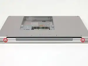
Rotate the computer 90 degrees and remove the two Phillips screws from the rear of the computer.
-
-
-
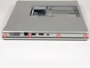
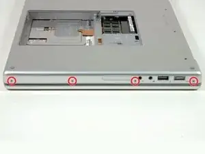
Rotate the computer 90 degrees again and remove the four Phillips screws from the side of the computer.
-
-
-
Lift up at the rear of the case and work your fingers along the sides, freeing the case as you go. Once you have freed the sides, you may need to rock the case up and down to free the front of the upper case. This stage can be quite tricky. Over the DVD reader are 4 tabs set back which pull out vertically.
-
Note that the two small tongues on the left hand front of the upper case may bend while you remove the upper case. When re-installing, you may need to bend them back to fit in the grooves in the lower case.
-
-
-
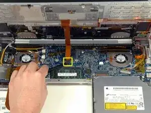
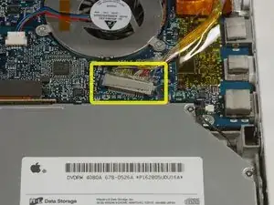
Disconnect the trackpad and keyboard ribbon cable from the logic board, removing tape as necessary.
-
Remove the upper case.
-
-
-
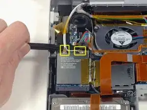
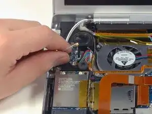
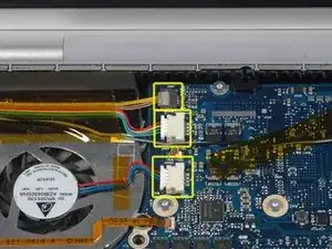
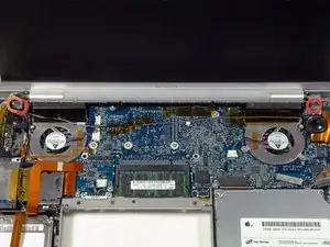
Disconnect the iSight, inverter, and left fan cables from the logic board by gently pulling in the direction of each cable.
-
-
-
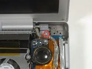
Remove the silver T6 Torx screw securing the ground loop on the display data cable to the casing.
-
-
-
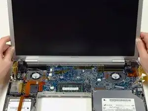
Support the display with one hand while removing the following 3 screws:
-
Two 9.5 mm silver T6 Torx screws with threads on only part of the shaft on the inside of the display hinges.
-
One 9.5 mm silver T6 Torx screw with threads on the entire shaft on the outside of the left hinge.
-
-
-
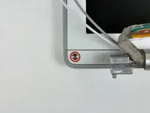
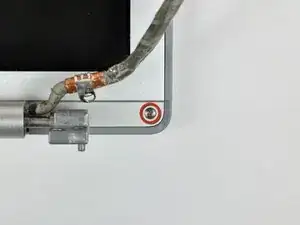
Remove the two 5 mm Phillips screws from the lower left and right corners of the display (two screws total).
-
-
-
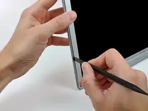
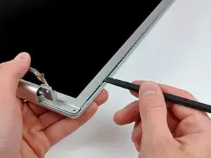
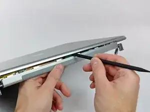
Insert the flat end of a spudger perpendicular to the face of the display between the plastic strip attached to the rear bezel and the front bezel.
-
With the spudger still inserted, rotate it away from the display to separate the front and rear bezels.
-
Work along the left edge of the display until the rear bezel is evenly separated from the front bezel.
-
-
-
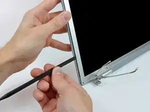
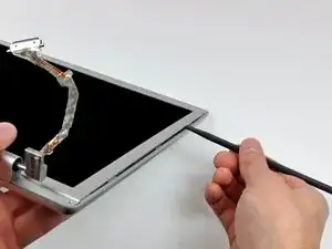
Insert the flat end of a spudger perpendicular to the face of the display between the plastic strip attached to the rear bezel and the front bezel.
-
With the spudger still inserted, rotate it away from the display to separate the front and rear bezels.
-
Work along the right edge of the display until the rear bezel is evenly separated from the front bezel.
-
-
-
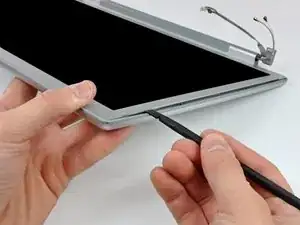
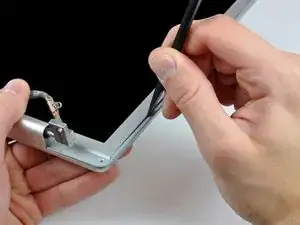
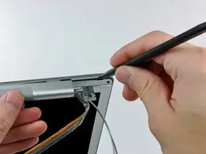
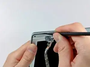
Insert the flat end of a spudger between the front bezel and the plastic strip attached to the rear bezel near the screw holes at the bottom corners of the display.
-
Rotate your spudger toward the rear bezel to separate it from the front bezel.
-
If necessary, enlarge the gap between the lower edge of the rear bezel and the clutch cover until the two components are completely separated.
-
-
-
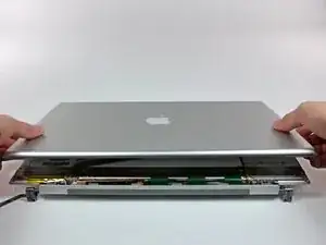
Lift the rear bezel by its bottom edge and rotate it away from the display assembly to separate the top edge.
-
Remove the rear display bezel from the display assembly.
-
-
-
Disconnect the LCD backlight from the inverter by pulling its connector away from the inverter board.
-
-
-
Disconnect the inverter cable by pulling its connector away from the socket on the inverter.
-
-
-
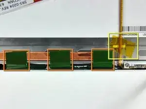
Remove the pieces of yellow kapton tape from the bottom left corner of the display.
-
Peel the three green antenna ground straps off the copper tape along the bottom edge of the LCD.
-
Remove the piece of tape securing the camera cable to the LCD.
-
-
-
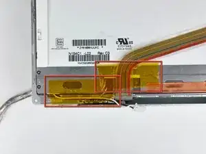
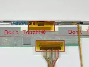
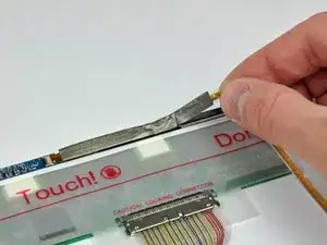
Remove the pieces of tape covering the display data cable and camera cable connectors.
-
Carefully peel the camera cable off the foam tape along the top edge of the LCD.
-
-
-
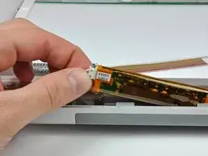
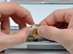
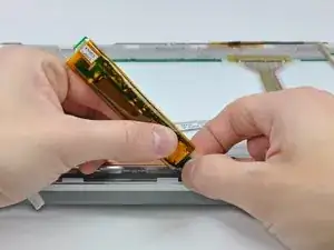
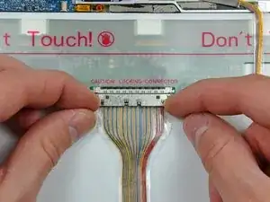
Gently pull the camera cable away from its socket on the camera board.
-
Pull the display data cable connector away from its socket on the LCD.
-
Pull both cables parallel to the face of the logic board.
-
-
-
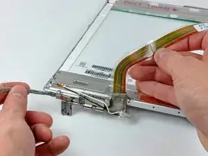
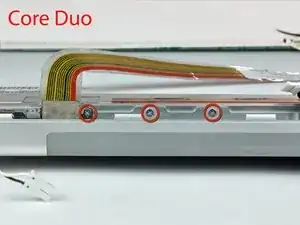
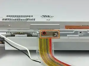
If you have a Core Duo machine, refer to picture 1 and remove three Phillips screws connecting the clutch assembly to the lower edge of the front display bezel near the display data cable.
-
If you have a Core 2 Duo Model A1211 machine, refer to picture 2 and remove two Phillips screws connecting the clutch assembly to the lower edge of the front display bezel near the display data cable.
-
-
-
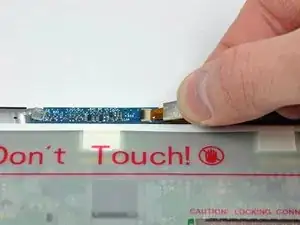
Remove the small Phillips screw from behind the display data cable.
-
Remove the small rectangular steel bracket by sliding it away from the right clutch hinge.
-
-
-
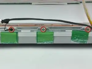
Remove three Phillips screws attaching the clutch assembly to the lower edge of the front display bezel.
-
-
-
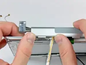
Push the open edge of the clutch cover away from the left clutch hinge to pop it off the clips attaching the two parts.
-
Remove the clutch assembly from the front display bezel.
-
-
-
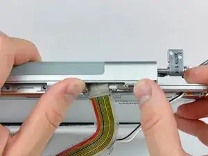
De-route the display data cable from around the right clutch hinge and remove it from the front bezel.
-

To reassemble your device, follow these instructions in reverse order.

Un commento
Thanks you’ve been a great help.
Before beginning, I found some small plastic bags and labeled each of the with the location the screws would come from once removed and the appropriate step number. Once the screws were removed I placed them in the labeled bags and did not have to worry about mixing screws up. Also, provided a good way to insure that no steps were skipped in the reverse process
rpbetancourt -
If you don't have any plastic bags, you can always print out the photos in black and white as you go, and then tape the screws on to the print outs over the circles that denote the screw positions in the photos. This method helps get every single screw back in it's exact location, even months after a tear down. ;o)
Adam -
Thank you very much!
Evgeniy -
When I did this, I used a empty egg carton to store my screws. I wrote the steps where I removed screens in Sharpie on the bottom of the "egg cup" and then dropped the screws in as I went. Then I just worked backwards to put it all back together.
mark93 -
I Generally just use a piece of paper with a rough sketch of the system and locations of the screws with prestik.
Tarn Alcock -