Introduzione
This detects the internal temperature of your machine for heat management.
-
-
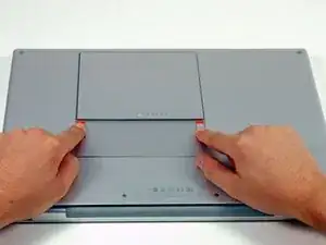
Use your fingers to push both battery release tabs away from the battery, and lift the battery out of the computer.
-
-
-
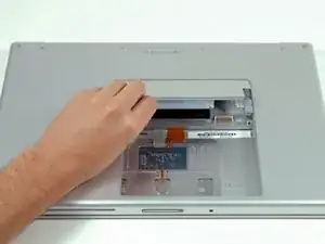
Lift the memory door up enough to get a grip on it, and slide it toward you, pulling it away from the casing.
-
-
-
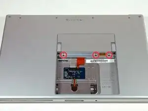
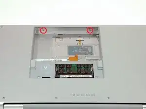
Remove the following 6 screws:
-
Two 10 mm T6 Torx screws on either side of the RAM slot.
-
Four 14.5 mm Phillips screws along the hinge.
-
-
-
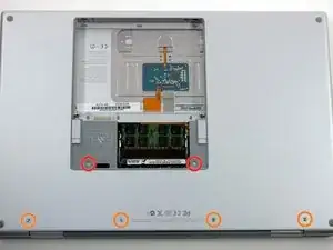
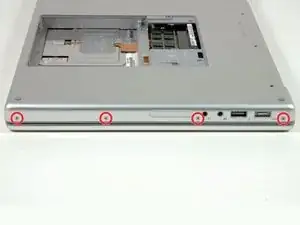
Rotate the computer 90 degrees and remove the two Phillips screws from the rear of the computer.
-
-
-
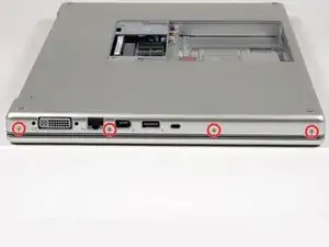
Rotate the computer 90 degrees again and remove the four Phillips screws from the side of the computer.
-
-
-
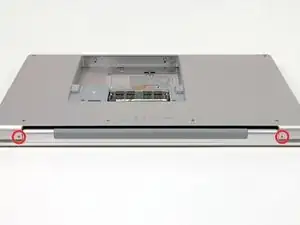
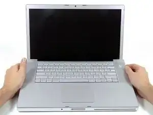
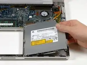
Lift up at the rear of the case and work your fingers along the sides, freeing the case as you go. Once you have freed the sides, you may need to rock the case up and down to free the front of the upper case. This stage can be quite tricky. Over the DVD reader are 4 tabs set back which pull out vertically.
-
Note that the two small tongues on the left hand front of the upper case may bend while you remove the upper case. When re-installing, you may need to bend them back to fit in the grooves in the lower case.
-
-
-
Disconnect the trackpad and keyboard ribbon cable from the logic board, removing tape as necessary.
-
Remove the upper case.
-
-
-
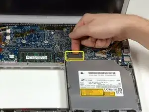
Disconnect the orange SuperDrive ribbon cable from the logic board, removing tape as necessary.
-
-
-
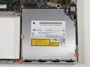
Remove the following 3 screws:
-
Two 3.3 mm silver Phillips screws on either side of the SuperDrive.
-
One 4.8 mm black Phillips screw at the top right corner of the drive.
-
The 4.8mm screw may be a T6 Torx
-
-
-
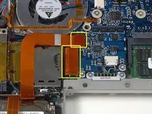
Disconnect the hard drive and ExpressCard connectors from the left side of the logic board.
-
-
-
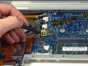
Disconnect the eight indicated connectors from the logic board, removing tape as necessary.
-
-
-
Use a spudger to flip up the brown plastic flap securing the left ambient light sensor cable to the logic board.
-
Slide the left ambient light sensor cable to the left and out of its connector.
-
-
-
Remove the silver T6 Torx screw securing the ground loop on the display data cable to the casing.
-
-
-
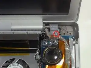
Remove the single silver T6 Torx screw securing the clear plastic shield over the right ambient light sensor.
-
Lift the clear plastic shield off the right ambient light sensor.
-
-
-
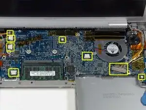
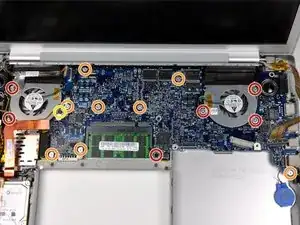
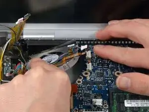
Remove the following 16 screws, moving cables as necessary:
-
One 4.4 mm black Phillips screw to the right of the RAM slot.
-
Nine 4.7 mm silver T6 Torx screws securing the logic board to the lower case.
-
One 6.2 mm black T6 Torx screw on the right side of the left fan.
-
Five 9.4 mm silver T6 Torx screws securing the left and right fans.
-
-
-
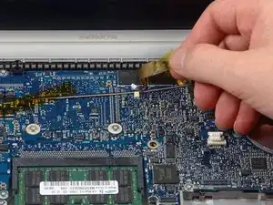
Move the display data cable to the right, removing tape as necessary.
-
Peel up and remove the orange foil shield near the right speaker.
-
-
-
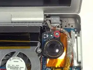
Rotate the speaker clockwise approximately 30 degrees until it comes free from the logic board.
-
-
-
Peel up the gray and black speaker wires from the top of the logic board, removing tape as necessary.
-
-
-
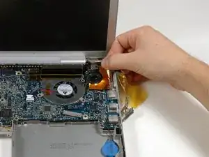
Peel up the iSight and inverter board cables from above the left fan.
-
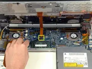
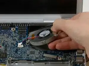
Hold the logic board down with one hand and use your other hand to lift the left fan up from its housing. There is a piece of black tape securing the fan to the heat sink. Carefully peel this tape up from the heat sink as you lift the fan up.
-
Place the fan above the Airport card. It is not necessary to entirely remove the fan from the computer.
-
-
-
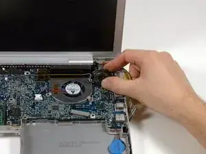
Lift the right fan up while carefully peeling up the tape which secures the fan to the heat sink.
-
Remove the right fan from the computer.
-
-
-
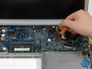
Lift up the left side of the logic board and disconnect the multi-colored power cable from the bottom of the board.
-
-
-
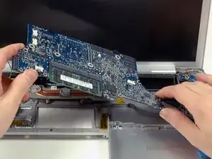
Grasp the logic board at the left side and at the thin section, and rotate the logic board out of the lower case.
-
-
-
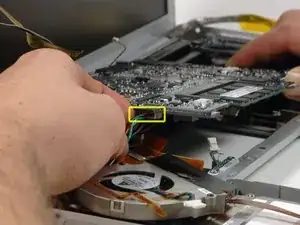
Disconnect the right thermal sensor cable from the bottom of the logic board near the DVI port.
-
-
-
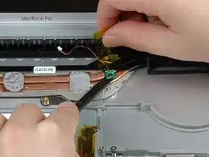
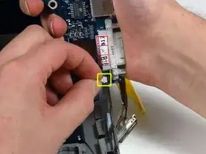
Peel back the orange Kapton tape covering the left thermal sensor.
-
Use a spudger to pry the left thermal sensor off the heat sink.
-
To reassemble your device, follow these instructions in reverse order.

Before beginning, I found some small plastic bags and labeled each of the with the location the screws would come from once removed and the appropriate step number. Once the screws were removed I placed them in the labeled bags and did not have to worry about mixing screws up. Also, provided a good way to insure that no steps were skipped in the reverse process
rpbetancourt -
If you don't have any plastic bags, you can always print out the photos in black and white as you go, and then tape the screws on to the print outs over the circles that denote the screw positions in the photos. This method helps get every single screw back in it's exact location, even months after a tear down. ;o)
Adam -
Thank you very much!
Evgeniy -
When I did this, I used a empty egg carton to store my screws. I wrote the steps where I removed screens in Sharpie on the bottom of the "egg cup" and then dropped the screws in as I went. Then I just worked backwards to put it all back together.
mark93 -
I Generally just use a piece of paper with a rough sketch of the system and locations of the screws with prestik.
Tarn Alcock -