Introduzione
If you use a power adapter which is to weak for your Mac Book (e.g. 60W for a MBP 15" which is specified for a 80W power adapter) the following should happen from a theoretical point of view: The power adapter is overloaded and heats up until the internal thermal protection switches it off savely. -- And this happened in real live: The adapter blew up in a way, that it delivered one last powerful current pulse which also destroyed parts of the logic board. The Mac Book is still fully operational with battery, but can not be charged nor powered any more, even with a new power adapter.
The disassembling steps are referenced to MacBook Pro 15" Unibody Mid 2010 Logic Board Replacement. For this particular guide it is not necessary to unmount the fans, heatpipes and speaker-microphone-block. Just skip the related steps.
Since the topology of the circuit between power connector and battery is common technique, this guide might fit to other logic boards too.
Ricambi
-
-
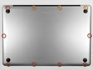
Remove the following ten screws securing the lower case to the upper case:
-
Three 13.5 mm (14.1 mm) Phillips screws.
-
Seven 3 mm Phillips screws.
-
-
-
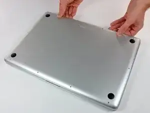
Using both hands, lift the lower case near the vent to pop it off two clips securing it to the upper case.
-
Remove the lower case and set it aside.
-
-
-
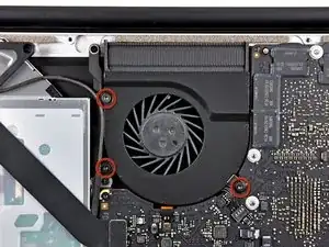
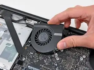
Use the flat end of a spudger to pry the right fan connector up out of its socket on the logic board.
-
Remove the right fan from the upper case.
-
-
-
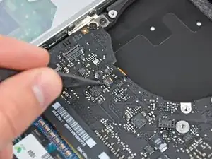
Use the flat end of a spudger to pry the AirPort / Bluetooth ribbon cable up off its socket on the logic board.
-
-
-
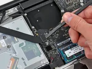
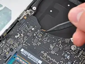
Use the flat end of a spudger to pry the optical drive cable connector up from the logic board.
-
-
-
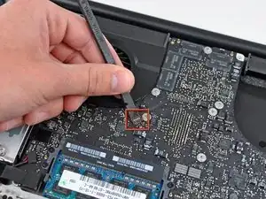
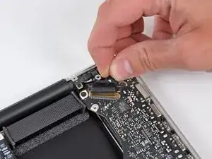
Carefully pull the subwoofer/right speaker cable up to lift its connector out of its socket on the logic board.
-
-
-
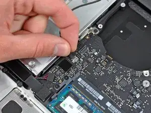
Use the flat end of a spudger to pry the hard drive cable connector up out of its socket on the logic board.
-
-
-
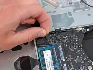
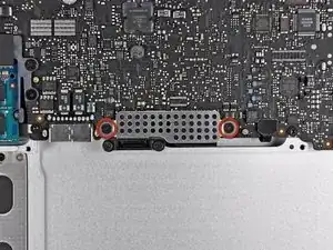
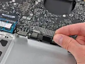
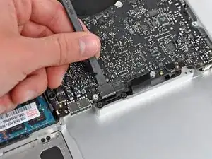
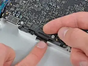
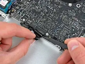
Remove the two short Phillips screws securing the small EMI shield to the logic board.
-
Remove the EMI shield from the logic board.
-
-
-
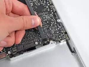
Use the flat end of a spudger to pry the trackpad cable connector up out of its socket on the logic board.
-
-
-
Use your fingernail to carefully flip up the keyboard ribbon cable retaining flap.
-
Use the tip of a spudger to pull the keyboard ribbon cable straight out of its socket.
-
-
-
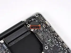
Use the flat end of a spudger to pry the battery indicator cable connector up out of its socket on the logic board.
-
-
-
Grab the plastic pull tab secured to the display data cable lock and rotate it toward the DC-In side of the computer.
-
Pull the display data cable straight out of its socket.
-
-
-
Use the tip of a spudger or your fingernail to flip up the retaining flap on the keyboard backlight ribbon cable socket.
-
Pull the keyboard ribbon cable straight out of its socket.
-
-
-
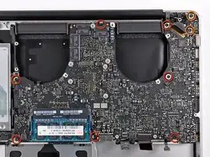
Remove the following screws:
-
Seven 3.3 mm T6 Torx screws securing the logic board to the upper case.
-
Two 8 mm T6 Torx screws securing the DC-In board to the upper case.
-
-
-
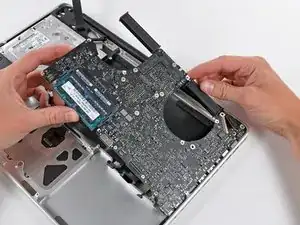
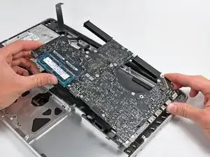
Carefully lift the logic board assembly from the left side and work it out of the upper case, minding the port side that may get caught during removal.
-
-
-
Lift the logic board enough to gain clearance and use a spudger to pry the microphone up off the upper case.
-
-
-
Slide the logic board away from the port openings and lift the assembly out of the upper case.
-
-
-
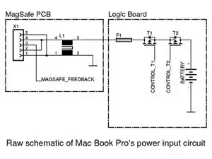
The picture shows a schematic which is similar to Mac Book Pro's power input circuit. The series components L1, F1, T1, T2 have to draw the full power, so those are of interest for us. With an ohmmeter you can check these parts.
-
L1: Since I could not figure out the manufacturer of this common mode choke I recommend to use a new MagSafe PCB.
-
F1: According to the printing on this part it is very likely that this is a Littelfuse 0469006 6A fuse.
-
T1, T2: Both MOSFETs are HAT1128R type. Since this part is obsolete I took IRF9317PbF
-
-
-
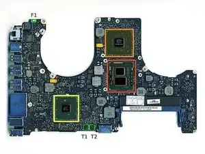
The picture shows where the relevant parts are placed on the logic board. F1, T1 and T2 are marked green. L1 is mounted on the MagSafe PCB and so not seen on the picture.
-
After you have figured out which of these parts (L1, F1, T2, T2) are defective you can change them. I recommend to replace both MOSFETs if there is at least one damaged.
-
After replacing the defective parts you can check the functionality by connecting the battery and the power adapter to the logic board. If everything is fine the LED of the MagSafe connector will light up green and switch to orange if battery will be charged. Be very careful.
-


To reassemble your device, follow the prerequisited guide in reverse order.
7 commenti
I don't know if any 80w MagSafe. It should be 85w for 15" and 60w for 13"...
Is there any chance you would be able to show the location of these parts if the same thing happened on a 2012 MacBook Pro Retina? I've been trying to find the information for a couple days now. Thank you
Nick -
Great post! Thank you!