Introduzione
No power to the laptop? Replace the DC-in Board.
Strumenti
Ricambi
-
-
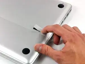
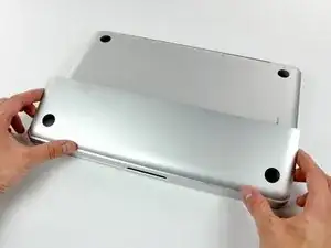
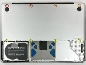
With the case closed, place the Unibody top-side down on a flat surface.
-
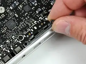
Depress the grooved side of the access door release latch enough to grab the free end. Lift the release latch until it is vertical.
-
-
-
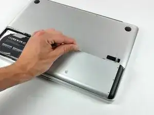
Remove the following eight screws securing the lower case to the chassis:
-
One 3 mm Phillips screw.
-
Three 13.5 mm Phillips screws.
-
Four 3.5 mm Phillips screws.
-
-
-
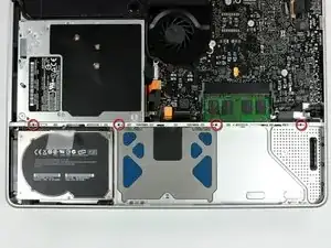
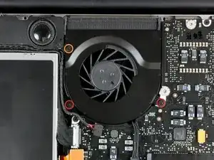
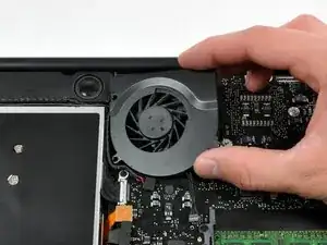
Remove the following three screws securing the fan to the upper case:
-
Two 5 mm Phillips screws.
-
One 7 mm Phillips screw.
-
-
-
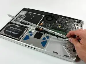
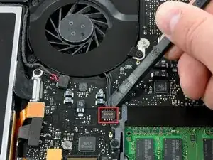
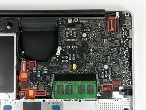
Each connector is different, so the following steps will show you how disconnect each in detail.
-
-
-
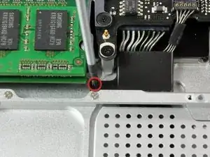
Remove the single Phillips screw securing the battery cable cover to the upper case.
-
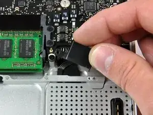
Remove the battery cable cover from the upper case.
-
-
-
Use a spudger to pry the battery level indicator cable connector straight up off the logic board.
-
-
-
Using the tip of a spudger, flip up the keyboard ribbon cable retaining flap.
-
Pull the keyboard ribbon cable straight out of its socket.
-
If the smaller connector at the right side of the keyboard ribbon cable is populated by another small black ribbon cable, remove it in a similar way to the above.
-
-
-
Use the flat end of a spudger to pry the trackpad connector straight up off the logic board.
-
-
-
Use the tip of a spudger to flip up the locking lever to release the IR sensor ribbon cable from its socket.
-
Use the tip of a spudger to pull the IR sensor ribbon cable straight away from the logic board.
-
-
-
Use the flat end of a spudger to pry the hard drive cable connector straight up off the logic board.
-
-
-
Use the flat end of a spudger to pry the optical drive cable connector straight up off the logic board.
-
-
-
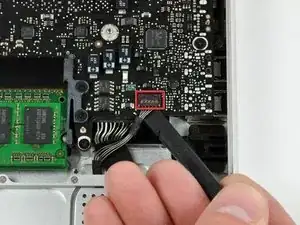
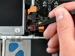
Use the flat end of a spudger to pry the subwoofer cable connector straight up off the logic board.
-
-
-
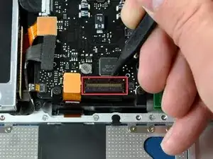
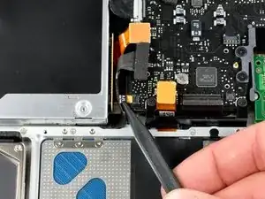
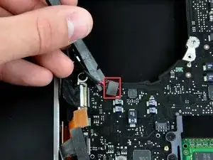
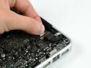
Grab the plastic pull tab secured to the display data cable lock and rotate it toward the DC-in side of the computer.
-
Pull the display data cable connector straight away from its socket.
-
-
-
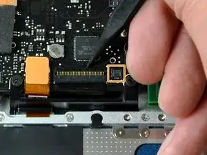
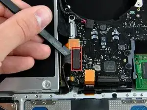
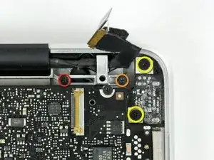
Remove the following two screws securing the display data cable bracket to the upper case:
-
One 7mm Phillips screw.
-
One 5mm Phillips screw.
-
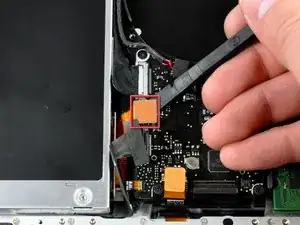
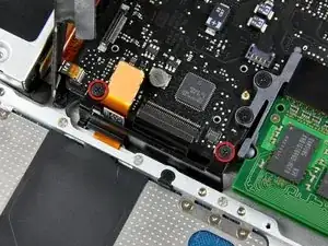
Remove the two 7 mm Phillips screws from the DC-in board.
-
Lift the display data cable bracket out of the upper case.
-
-
-
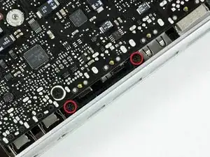
If present, remove the two 4mm Phillips screws securing the bottom case clip to the upper case.
-
Lift the bottom case clip out of the upper case.
-
-
-
Remove the two 5mm Phillips screws securing the keyboard flex bracket to the upper case.
-
Lift the keyboard flex bracket out of the upper case.
-
-
-
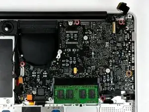
Remove the following five screws securing the logic board to the upper case:
-
Four 3mm Phillips screws.
-
One 3.5mm Phillips screw.
-
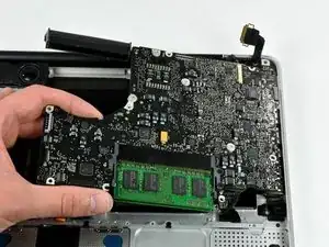
Lift the logic board from its left edge and pull it out of the upper case.
-
-
-
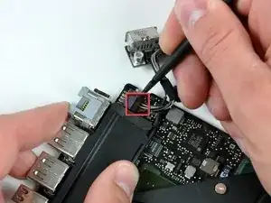
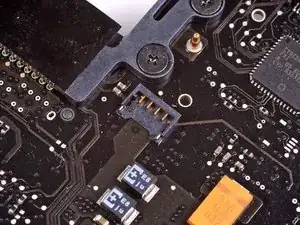
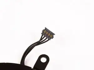
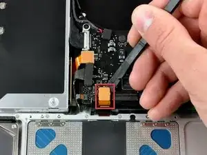
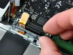
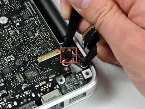
Disconnect the DC-In Board connector from the logic board by pulling it straight away from its socket.
-


To reassemble your device, follow these instructions in reverse order.

Un commento
Hello, how I know that DC-In Board it´s the problem and not other part of my macbook? The magsafe is ok. Thanks!
pablo -
This is not a a1278 unibody MacBook Pro. A1278 MacBooks backs are one solid metal piece not two separate pieces. This guide is for a different MacBook Pro.
Brad Burgeson -
This guide isn’t for a pro; it’s a MacBook unibody.
Nicholas -
So, it turns out that Apple used the model code A1278 for quite a few different Mac models, including both Pro and non-Pro versions! This guide is for the non-Pro Macbooks. There’s also one for the Pro models with the same A1278 identifier.
tempelmann -