Introduzione
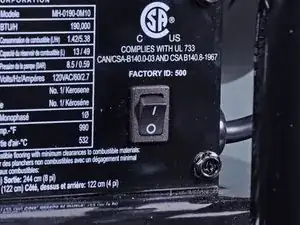
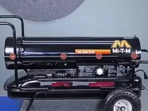
Follow this guide to replace the ignitor on a Mi-T-M heater model MH-0190-0M10.
After the pump and motor are reinstalled, use a flat blade screwdriver to adjust the pump pressure to 7.5 PSI as instructed on page 17 of the user manual.
-
-
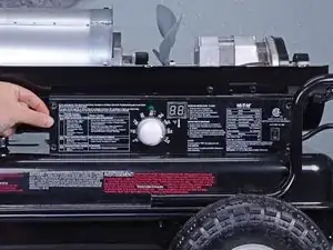
Flip the power switch into the OFF position.
-
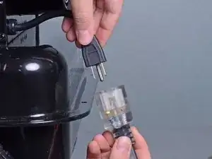
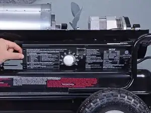
Unplug any extension cords from the included power cord.
-
-
-
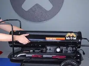
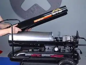
Use a 5/16 inch socket or Phillips screwdriver to remove the eight screws securing the upper shell, four on each side.
-
-
-
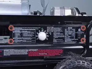
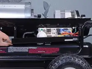
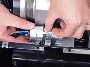
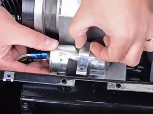
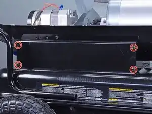
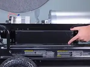
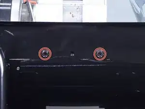
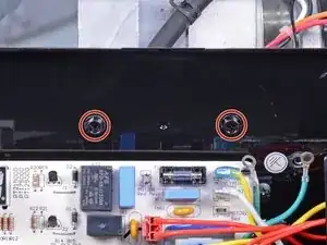
Use a 5/16 inch socket or Phillips screwdriver to remove the four bolts securing the right-side cover.
-
-
-
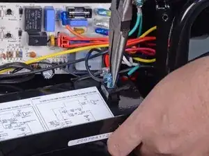
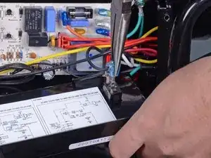
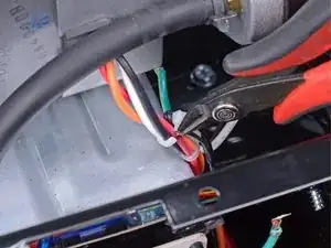
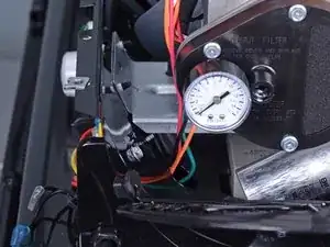
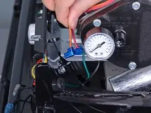
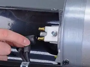
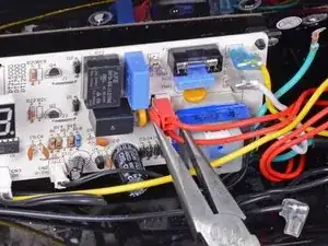
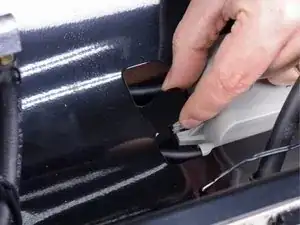
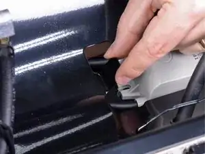
Use needle nose pliers to remove the wire with the blue connector.
-
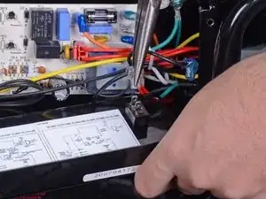
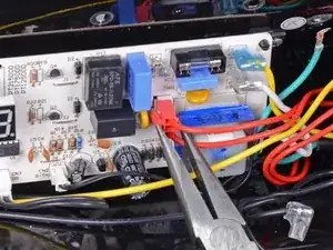
Remove the wire with the clear connector.
-
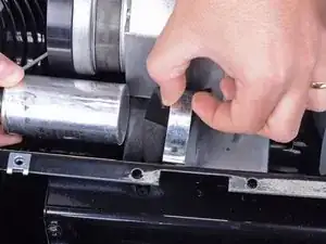
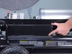
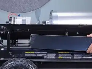
Remove the right-side cover.
-
-
-
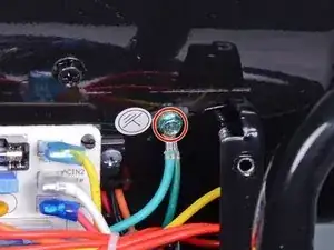
Use a 5/16 inch socket or Phillips screwdriver to remove the screw securing the two green ground wires to the frame.
-
-
-
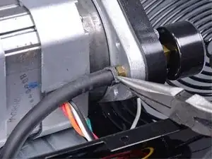
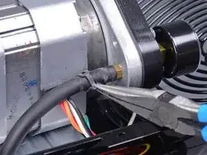
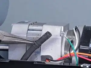
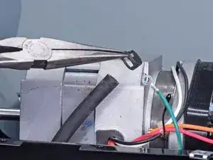
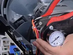
Use a pair of needle nose pliers to release the hose clamp from the fuel line.
-
Slide the hose clamp off of the nipple, about one inch down the fuel line.
-
-
-
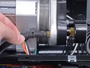
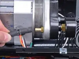
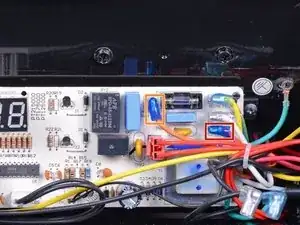
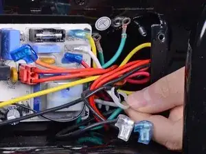
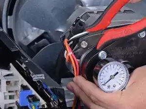
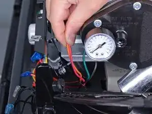
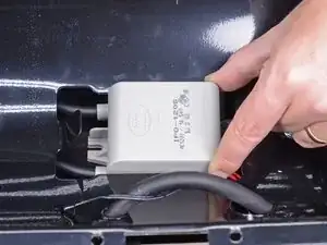
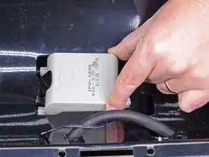
Use a pair of needle nose pliers to disconnect the wires connecting the motor and pump assembly to the main PCB board:
-
One red cable labeled MOTOR 2 on the main PCB board
-
One orange cable labeled MOTOR 1 on the main PCB board
-
-
-
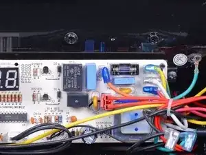
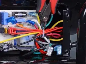
Use a pair of flush cutters to cut the cable tie harnessing the wires running from the main PCB assembly.
-
Remove the cable tie.
-
-
-
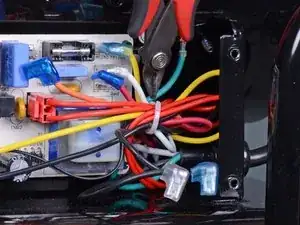
Use a pair of flush cutters to cut the cable tie harnessing the orange, red, white, and black wires near the fuel line.
-
-
-
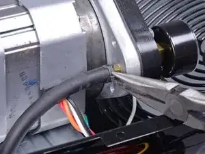
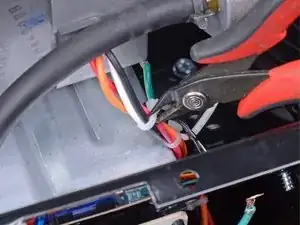
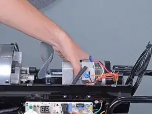
Use a pair of flush cutters to cut the cable tie harnessing the orange and red wires next to the motor.
-
-
-
Use a 5/16 inch socket or Phillips screwdriver to remove the four bolts securing the left-side cover.
-
-
-
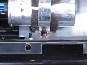
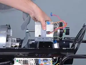
Use a 5/16 inch socket or Phillips screwdriver to remove the four screws securing the motor mount bracket, two on each side.
-
-
-
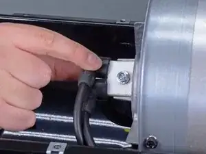
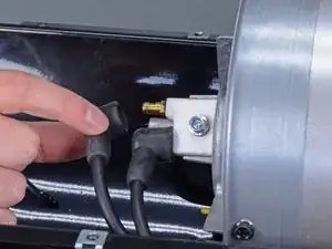
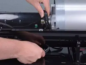
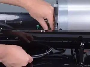
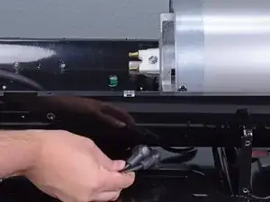
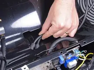
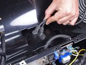
Grab the spark plug wires by their boots and pull firmly to disconnect them from the spark plug.
-
-
-
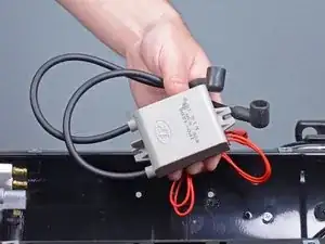
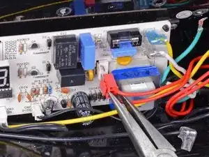
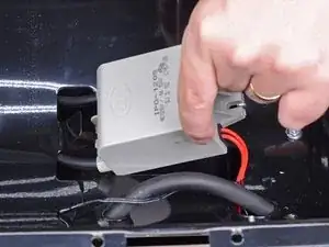
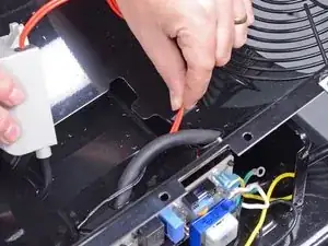
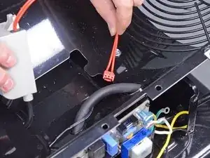
Use a pair of needle nose pliers to depress the locking tab on the red wiring harness's connector labeled IG on the main PCB assembly.
-
With the locking tab depressed, pull to remove the red wire from its header on the PCB.
-
-
-
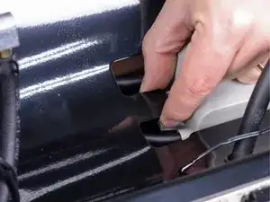
Use your fingers to bend the metal tab on the lower shell holding the igniter in place upward to create space for the igniter to be removed.
-

To reassemble your device, follow these instructions in reverse order.