Introduzione
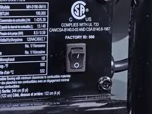
Follow this guide to replace the main PCB assembly on a Mi-T-M heater model MH-0190-0M10.
-
-
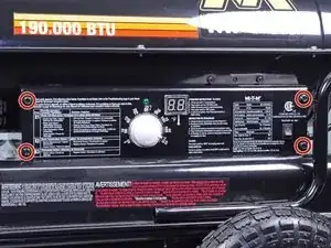
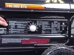
Flip the power switch into the OFF position.
-
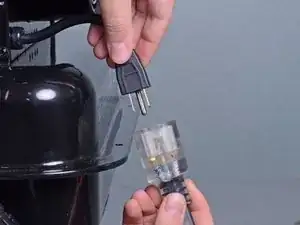
Unplug any extension cords from the included power cord.
-
-
-
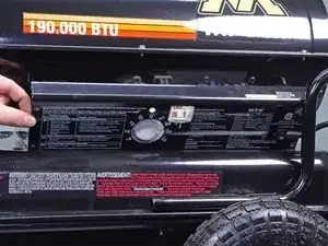
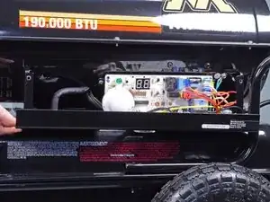
Use a 5/16 inch socket or Phillips screwdriver to remove the four bolts securing the right-side cover.
-
-
-
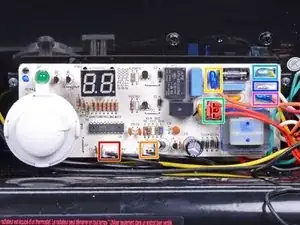
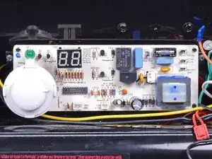
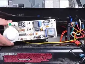
Disconnect all wires from the main PCB assembly:
-
The photocell wire connector labeled CN3 on the board
-
The white wire connector labeled CN2 on the board
-
The orange wire labeled MOTOR1 on the board
-
The igniter wire connector labeled CN1 on the board
-
The yellow wire labeled ACIN1 Yellow on the board
-
The white wire labeled ACIN2 White on the board
-
The red wire labeled MOTOR2 Red on the board.
-
-
-
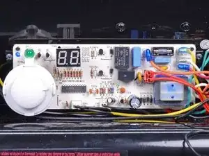
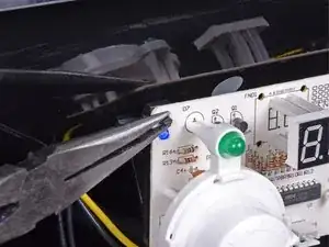
Use a pair of pliers to depress the locking tabs on one of the corner retaining clips securing the PCB to the bracket.
-
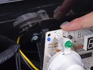
With the locking tabs depressed, pull the PCB away from the bracket to remove the corner.
-
Repeat for the three remaining retaining clips.
-

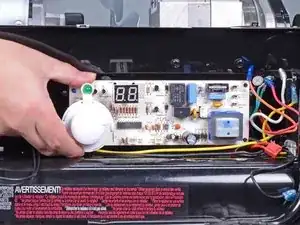
To reassemble your device, follow these instructions in reverse order.