Introduzione

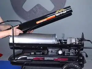
Follow this guide to replace the photocell on a Mi-T-M heater model MH-0190-0M10.

  1. YRbIqSAM36IanG1s
    YRbIqSAM36IanG1s
    YiwWQ4jHxTGCAfbx
    • Power off the machine at least one hour prior to starting repairs. Ensure the machine is completely cool to the touch.

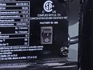
    • Flip the power switch into the OFF position.

    • Unplug any extension cords from the included power cord.

  2. BCnDXObnU4aLlUnw
    BCnDXObnU4aLlUnw
    FLPeVeegkam51uFt
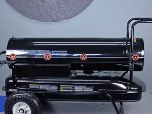
    • Use a 5/16 inch socket or Phillips screwdriver to remove the eight screws securing the upper shell, four on each side.

  3. g3goHXdvbgJkfYnr
    g3goHXdvbgJkfYnr
    kk5TiRy4kNpsgEAK
    • Lift the upper shell straight up off of the machine to remove it.

  4. QgXOps5UNWMx26Kw
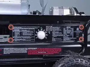
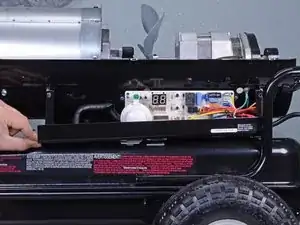
    • Use a 5/16 inch socket or Phillips screwdriver to remove the four bolts securing the right-side cover.

  5. uqNbUREyKHZtrCZZ
    uqNbUREyKHZtrCZZ
    At6qgsDHeHEERmKO
    eBoB3rmIPhOQgVco
    • Tilt the right-side cover down to access the PCB board.

    • Do not fully remove the right-side cover, it is still attached via the on/off switch.

    • During reassembly, ensure the display window is aligned with the LCD display before you press the cover into place.

  6. dQqwMw1xAdemtLct
    dQqwMw1xAdemtLct
    MlXd6KO1SdtlEVpa
    EI3O1ZuBfSuFHOOL
    • There are two wires connecting the power switch to the main PCB assembly.

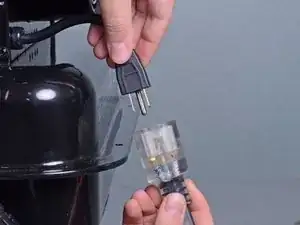
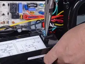
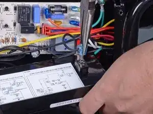
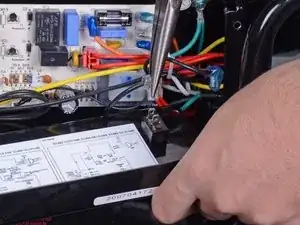
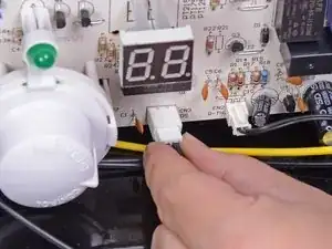
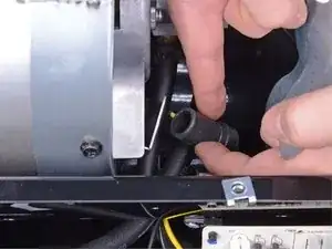
    • Use needle nose pliers to remove the wire with the blue connector.

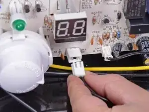
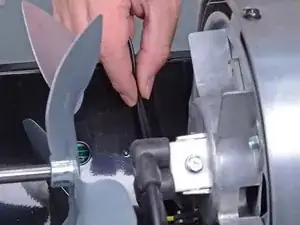
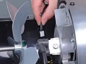
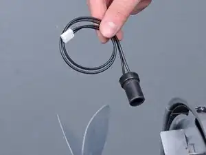
    • Remove the wire with the clear connector.

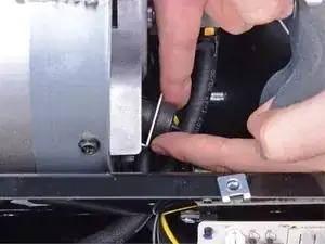
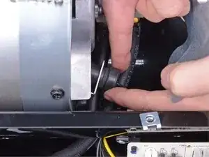
    • Remove the right-side cover.

    • During reassembly, install the power switch wires back in their original locations with the blue wire above the clear wire.

  7. UbPjYIINbVhOw5VW
    UbPjYIINbVhOw5VW
    VFwWxGIOpVnOUrAe
    • Use your fingers to disconnect the white wire harness labeled CN3 on the main PCB assembly.

  8. MfCkC1RJktmWZYQG
    MfCkC1RJktmWZYQG
    tDMYlmQeY4BLYGZZ
    BGbqBkSkTFOorruF
    • Use your fingers or a pair of pliers to remove the photocell from its bracket.

    • During reassembly, ensure the photocell sits flush around the entire perimeter of the bracket.

  9. BIckeDBSPVGS6AoA
    BIckeDBSPVGS6AoA
    NmkuvHDLoIyUbOZj
    YAektWndpyWQMlbH
    • Feed the photocell wires through the opening in the lower cover.

    • Remove the photocell.

Conclusione

To reassemble your device, follow these instructions in reverse order.

Sam Omiotek

Membro da: 25/02/19

71915 Reputazione

0 commenti