Introduzione
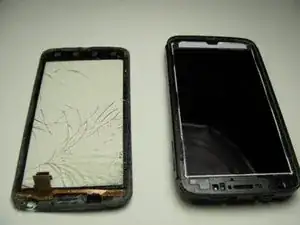
Use this guide to replace the screen of the Motorola Atrix 4G. To remove the screen you will first need to remove the battery, open the phone and remove the motherboard. Be ready to use a plastic opening tool, T5 Torx Screwdriver, spudger and head gun or hair dryer.
-
-
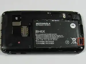
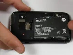
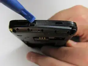
Insert a spudger or plastic opening tool into the small notch at the base of the battery.
-
Lift the battery out of the phone.
-
-
-
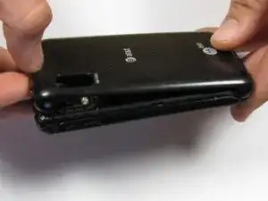
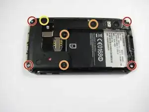
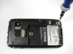
Remove the four 5.0 mm T5 Torx screws from the corners of the phone.
-
Remove three 5.5 mm T5 Torx screws from the back of the phone.
-
Lift up the black rubber flap near the SD card slot.
-
Remove the single 5.5 mm T5 Torx screw beneath the flap.
-
-
-
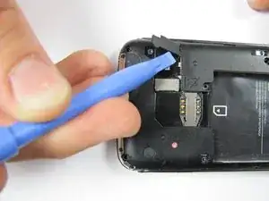
Remove the back case of the phone by gently lifting the tabs located on top of the phone near the lock button.
-
Use the case opener or spudger in these small areas because the plastic tabs can be easily broken.
-
Lift the tabs located on the bottom of the phone to continue removing the back cover.
-
-
-
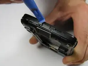
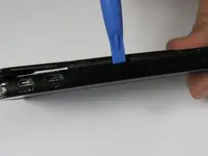
Slide an opening tool between the gap from the back of the case to the front.
-
After separating the sides, make sure there is a noticeable gap between the back case and the rest of the phone.
-
After detaching the tabs and sliding down the sides, there should be a noticeable gap between the front and back cases.
-
-
-
Carefully separate the back case from the rest of the phone by lifting it away from the phone.
-
-
-
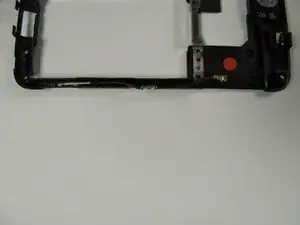
Ease the antenna from out of its guide along the side of the phone
-
Once the antenna is detached, remove the back case and the antenna from the phone
-
-
-
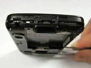
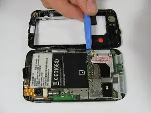
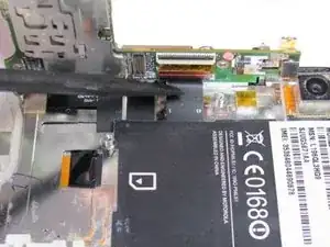
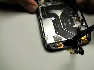
To remove the motherboard, first dislodge the right side of the motherboard, where the external connections are located, from the rest of the phone.
-
This can be done by placing a spudger in between the two ports on the phone, between the black plastic and motherboard, and prying out.
-
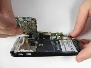
The motherboard should be able to be easily lifted upwards after dislodging it.
-
If the white rubber piece moves, replace it where it came from upon reassembly.
-
-
-
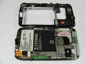
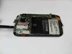
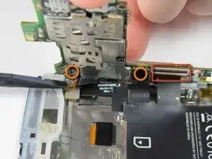
First, several connections must be disconnected to completely separate the motherboard from the rest of the phone.
-
The connection highlighted with a red box must be pulled down instead of out.
-
Using the spudger tool, separate the two connections on the motherboard highlighted with orange circles by pulling them out.
-
The black switch on top of this connection acts as a lock. Push it forwards to unlock the connection.
-
-
-
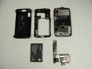
After disconnecting the motherboard, there should be five distinct and separate parts of the phone: back cover, back case, front case, battery, and motherboard.
-
-
-
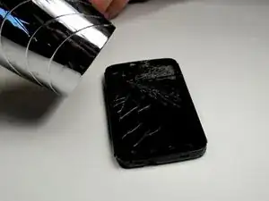
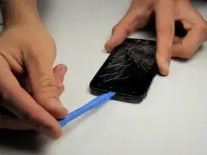
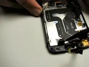
Using a heat gun or a hair dryer on high heat, soften the adhesive securing the glass screen.
-
-
-
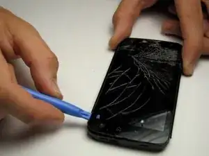
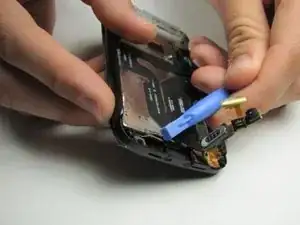
Using a plastic opening tool, carefully pry up the bottom of the display glass.
-
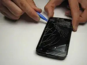
Slowly work your way around the phone, using the plastic opening tool to separate the glass from the phone.
-
-
-
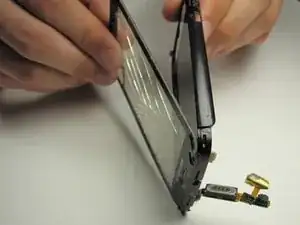
Now that the cable has been removed you can slide it through the opening and detach the glass.
-
Be careful as you pull the cable through the opening. The cable is easily damaged.
-
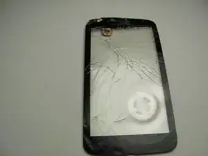
Once the cable is pushed through the slot, the glass can be fully removed.
-
To reassemble your device, follow these instructions in reverse order.
4 commenti
Caution! It is IMPOSSIBLE to insert the cable of the digitizer through the opening without REMOVING FIRST the screen (not the digitizer).
The two parts of the cable of the digitizer (connector + chip) are glued together when you remove the broken one, but in the replacement, if you glue together they don't pass trought the hole without removing the screen.
If someone has arrived to pass them without removing the screen, congratulations: I've broken the cable of a new screen in the process :(
I had to do this process twice, and here's what I've learned:
1) The motherboard does not need to be removed. I suspect this guide has you remove it so you don't damage any components when heating the screen, but there's no physical reason to remove it.
2) Yes, passing the digitizer cable/chip through the hole in the plastic housing is a royal PIA. I may have ruined the first screen I tried it with. Doh! For the second go round, instead of removing the LCD (like Hector recommends above), I just made the hole bigger. How, you ask? I took an emory nail file and trimmed it with scissors to be just narrower than the hole - then I filed away! With a few minutes of careful filing, I was able to double the size of the hole the cable has to pass through. Voila! There's still plenty of plastic left for the double-sided tape to be applied on the inside. Just be sure to clean up all the plastic dust first with a small vacuum or Q-tip before re-installing the screen.
Ben Lake -
tried this, broke first replacement digitizer screen , learned how to procede, Hector appears to be right if you remove the lcd screen it appears to double the size of the hole the cable passes through. what i would also like to see here are the following:
what material to use to "glue" the digitzer chip/connector together and in step 16 it shows the digitzer cable being removed from the metal it is attached to...how/what does one reattach it with?
Scott -
Did anyone ever answer how to glue the flat cable (ground?) back on?
Use the word "prying" rather than sliding. We were confused during this step.
Ben Sweeney -