Introduzione
This repair has steps that may result in device damage, please take care and use common sense while following steps. A video is included to provide more detail into the disassembly process if you run into any issues or are confused as to how the step is described.
This disassembly guide breaks down the Nest IQ Outdoor camera to the “module” level removing all electronics from the camera. It is likely that rather than designed to be easy to repair, the module structure was chosen for ease of assembly in the factory. The LED Ring “seal” of the camera does NOT seem to be designed to be re-opened. A specialized tool may need to be developed to prevent the “prying” method used in this guide.
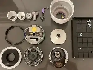
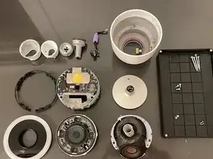
The modules/parts that the camera breaks down into are as follows:
- LED Light Ring
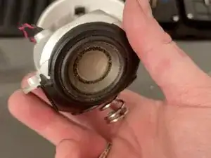
- Camera Module
- Motherboard Module
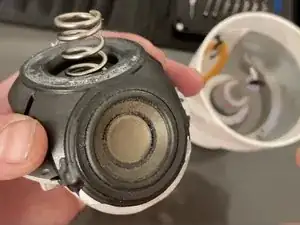
- Speaker Module (& Spring)
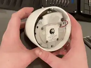
- Power Board
- Camera Shell/Housing
The writer of this guide and iFixit are not responsible for any damage caused to devices by the following of these steps.
-
-
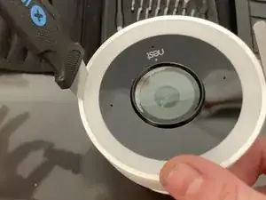
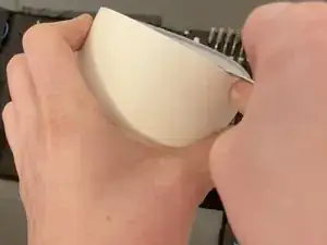
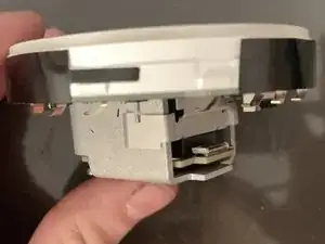
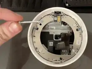
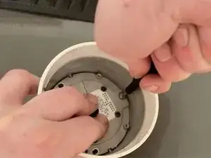
Carefully insert an iFixit "Jimmy" Tool (flat flexible steel blade) between the hard white plastic housing and edge of the LED light ring.
-
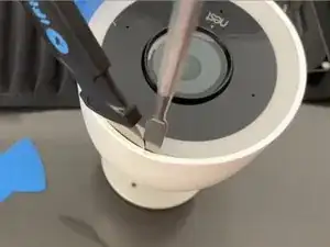
Pry the "Jimmy" tool slightly sideways and insert an iFixit "Metal Spudger" into the gap created. Slide it down inside the housing around half an inch.
-
Use the metal spudger to pry carefully slowly working your way in a circle around the LED Light ring to attempt to slowly work it backwards out of the housing.
-
-
-
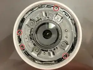
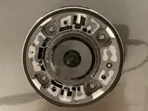
Remove each of the four screws securing the plastic ring that is holding down the camera module.
-
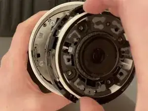
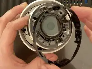
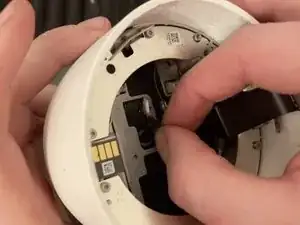
Pull the camera module upwards, and remove the black ring from around it by pulling it upward and over the camera module.
-
4 x 4.5(?)mm Torx T5 screws
-
-
-
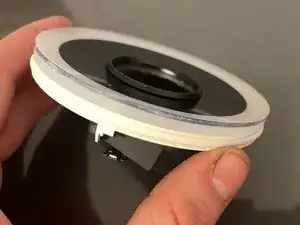
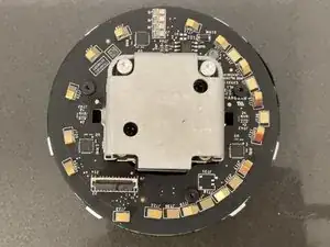
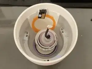
Lift the camera module up and out of the housing.
-
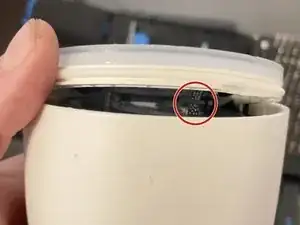
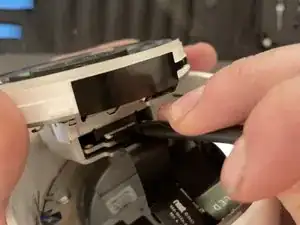
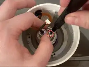
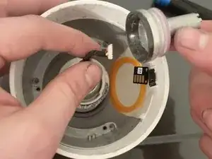
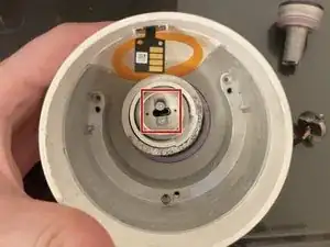
Using your fingernail pull down on the black portion of the ZIF connector to flip it into the down position.
-
Slide the LED ribbon cable out of the ZIF connector.
-
-
-
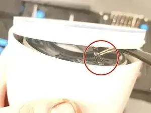
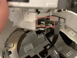
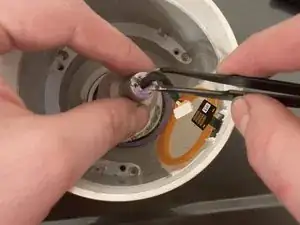
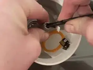
Using a flat plastic spudger push upwards on the black portion of the ZIF connector to flip it into the up position.
-
Slide the camera ribbon cable out from the connector.
-
-
-
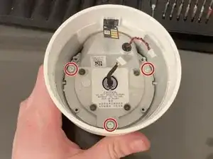
Remove the 4 long screws holding the motherboard module into the camera.
-
4 x 31mm Torx T9H screw
-
-
-
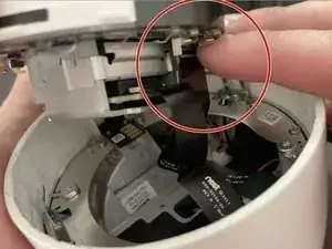
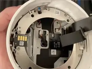
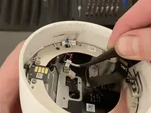
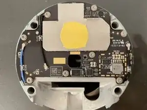
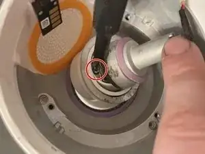
Using your fingers unplug the power connector by gently pulling upwards on the cable until the connector comes out of its socket.
-
-
-
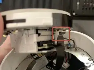
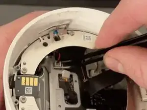
Unplug the speaker connector next to the power connector by gripping it with metal tweezers and gently pulling directly upward.
-
-
-
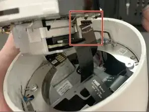
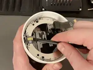
Using the flat spudger slide it under the power transfer pad to separate the glue holding the pad down.
-
Fold it up out of the way.
-
-
-
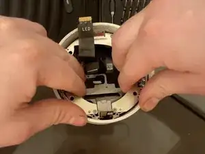
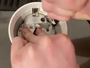
Using both hands, gently pull upwards making sure the power cable, speaker cable, and power pad route down through/around the motherboard module as you pull it upward.
-
-
-
Lift the Speaker Module and Spring out of the case, threading the power cable down through the middle.
-
-
-
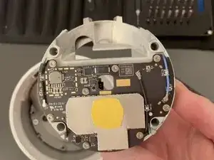
Bend/move the power cable to the side and remove each of the two screws holding down the Power Board.
-
2 x Torx T5 3(?)mm screws
-
-
-
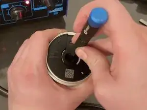
Using a pair of metal tweezers push on the two pink rubber bits on the top of the power cord housing and push downwards to slide the power cord out of the housing.
-
-
-
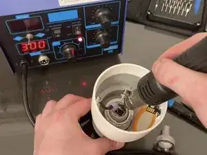
Using a heat gun melt the glue holding down the power board. The glue is placed directly under where the previous two screws were removed.
-
Using a thin tool (ideally a Male USB-C connector affixed to a rod) press out the power module. I do use the thinnest flathead screwdriver here to push on it, however this will likely damage the connector.
-
-
-
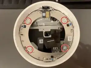
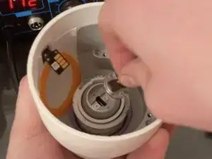
Remove the final two screws to release the base ball joint from the inside of the housing.
-
2 x Torx T5 3(?)mm screws
-
-
-
You are now done disassembling the unit to the module level! Check out the other guides (coming soon) to see how to break down the modules further.
-


To reassemble your device, follow these instructions in reverse order.
The Camera module and LED Ring should first be connected together with the microphones and status LED properly glued to the back of the LED Ring and the connectors are attached to the camera module.
When “re-sealing” the camera the Camera LED Ring combo assembly should be attached to the ribbon cables, then pressed/snapped down into place (into the black plastic ring with clips that hold down the camera module).
10 commenti
my power board has water damage. I'm trying to remove the board and direct wire it. any suggestions?
My power board also has water damage! Did you have any luck repairing yours? Cheers
If I cannot repair my power adapter, I'm considering parting mine out as there seems to be zero parts available.
I can't find the video link
fixit -
Do you have the link to the video available?
I will be attempting a tear down in a few weeks; wish me luck.
@skyyoung this is an awesome guide. I bought a bunch of these cameras a few years ago, thinking "they're expensive but they're very capable and I'll be set for many years to come." Boy, was I wrong....they've all been failing. I called Nest/Google (I'm super confused by their relationship but that's another story) and got ZERO satisfaction. So, I've switched to RING cameras. I don't have the time or desire to fix my Outdoor IQ cameras but I sure feel bad putting them in the landfill. If you'd be interested in 3 cameras (maybe 4 if my one remaining working camera dies) and a bunch of power adapters and cords), I'd be happy to ship them do you. I'm not a regular here on iFixit so, if you're interested, please email be directly... bob.stoney@comcast.net Thanks again for the work putting this step-by-step description together!
Robert Stoney -