Introduzione

If camera no longer works at all, then it might be time to replace the motherboard. Follow this guide to remove the motherboard from your camera.

  1. QEnwXiK4BOKVX6cO
    • Remove the three 3x3mm screws attached to the rear casing.

  2. LIuVAMKwoPyrLsS3
    • The panel can be identified by the wifi logo on its upper half on the camera's side.

    • Remove the 5x3mm screw holding down the panel on the side closest to the lens.

  3. R11E2FerpovSqcmQ
    • Pry the panel off from the bottom using your fingernail.

  4. sUusGvHZFXOrinl2
    • Remove the 3x2mm screw underneath the panel near the top of the camera.

  5. RkQaPoXgcnZfU2QV
    RkQaPoXgcnZfU2QV
    Ls4Ph4vHgEKHwFkw
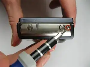
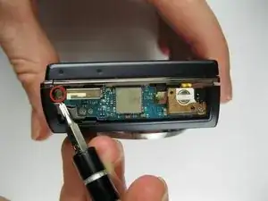
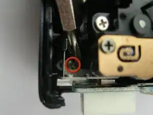
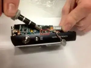
    • Remove the 4x3mm on the opposite side near the selector wheel.

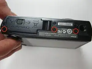
    • Remove the 2x2mm and 3x2mm screws underneath the a/v flap.

  6. QAcgbOXM3QChpOXf
    QAcgbOXM3QChpOXf
    kYZrQsoSoEmQTHMQ
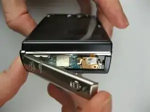
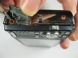
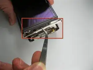
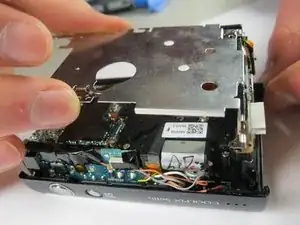
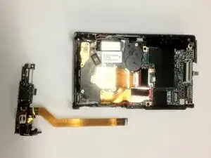
    • Pry the back panel away from the body of the camera, using the space you just opened up.

    • Be careful not to damage the ribbon cable on the opposite end of the camera.

    • A small piece of the frame of the camera may fall off, but it can be easily put back into place during reassembly.

  7. edoYfNNcvmK1HJAO
    edoYfNNcvmK1HJAO
    TE6oCanwH6k2sBeO
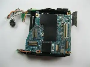
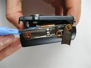
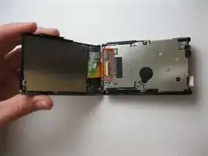
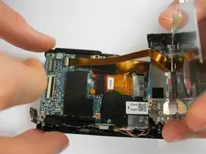
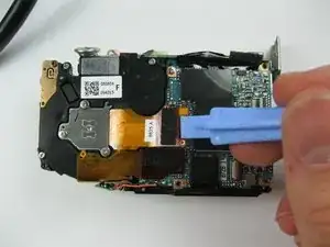
    • Pry up the plastic ribbon connectors on the body of the camera to release the ribbon cables.

    • The center connector is detached by flipping the black latch up and away from the center of the camera.

    • The smaller connector is detached by flipping the tan latch up and away from the edge of the camera.

  8. kEKYlRDUemtAnQjX
    • Remove the three 3x3mm screws that attach the front casing to the bottom.

  9. itrCUQH1wxHqZmJa
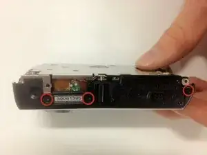
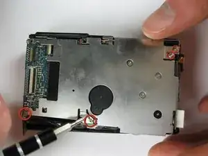
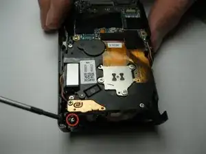
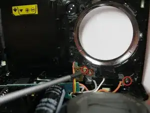
    • Remove the two 3x2 screws and two 3.5x2.5 screws attaching the rear panel to the motherboard.

  10. IO4ycDGlNQXfMOSN
    IO4ycDGlNQXfMOSN
    eFUjAeRW4S5bHisW
    • Lift the back panel off the motherboard.

    • Be careful not to damage the ribbon cable that attaches the mother board to the rear panel.

  11. 1oIAfFrZydJmq2lH
    1oIAfFrZydJmq2lH
    DHtVbRgUv6pWYxaf
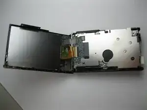
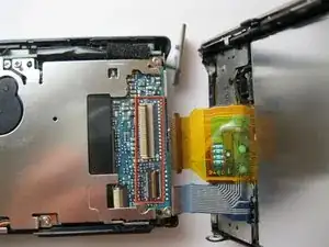
    • Detach the ribbon cable from the motherboard by flipping up the latch on the ribbon connector.

    • Note that the white ribbon connector latch flips away from the ribbon cable.

  12. JYEYnpECtCFsYOym
    JYEYnpECtCFsYOym
    dWGDAGHD3GaHPmFB
    • Remove the final 4x3mm screw at the top of the camera near the lens.

  13. QUYpCEsTwTNPPWiO
    QUYpCEsTwTNPPWiO
    DA3VZ4SpyUG4jEYo
    • Pry the front casing away from the body of the camera.

    • Be careful not to damage the wires that attach the front panel to the motherboard.

    • Short the leads on the capacitor near the flash to avoid a nasty shock when separating the casing from the body.

  14. kQAtKNXHKjXV3QF4
    • Unscrew the three 3x2mm screws that attach the cables to the front casing.

  15. UGPGUFDrX5qwIJtN
    UGPGUFDrX5qwIJtN
    HtfkM6bjhxOHgwZf
    • Pry up the ribbon connector that connects the ribbon cable to the lens assembly.

    • Take note that the ribbon connector pulls away from the ribbon.

  16. CkdoeFflKxdsVobD
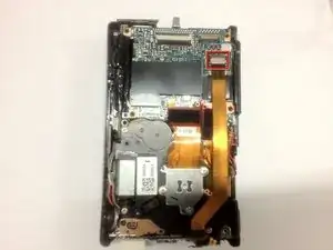
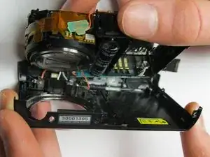
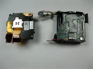
    • Once the lens assembly has been removed, the mother board cannot be disassembled any further.

Conclusione

To reassemble your device, follow these instructions in reverse order.

Kevin Backers

Membro da: 26/01/12

301 Reputazione

0 commenti