Introduzione
Replacing the LCD screen of a Nikon Coolpix 3500.
Strumenti
-
-
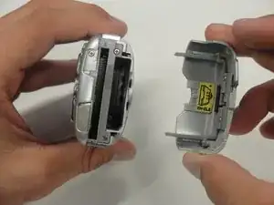
Unlatch the battery cover and slide the cover out. Place cover to the side, it will not be needed for the next few steps.
-
Remove the battery.
-
Remove the battery cover without using excessive force. Keep in mind this cover is fragile.
-
-
-
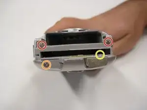
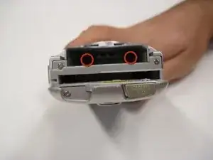
Remove the two 4.5 mm screws that sit next to the battery slot.
-
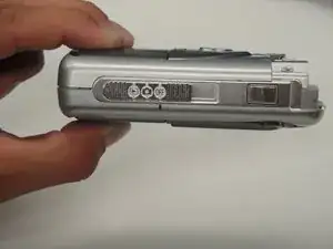
Remove the 3 mm screw that sits below the CF card slot.
-
Remove the 4.5 mm screw that sits above the digital I/O cover.
-
-
-
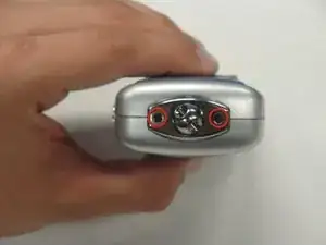
Remove the two 5 mm screws that sit near the camera strap eyelet.
-
Remove the camera strap eyelet.
-
-
-
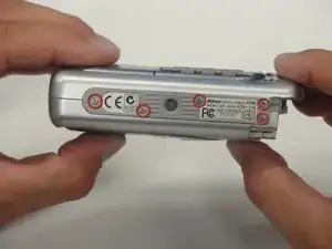
Remove the five 3.5 mm screws that sit at the bottom of the camera.
-
Remove the grey plastic piece, which the five screws held in place, by gently detaching the front cover.
-
-
-
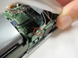
Using a spudger, detach the white-capped wire.
-
Using a spudger, detach the orange-capped wire and set the front cover aside.
-
-
-
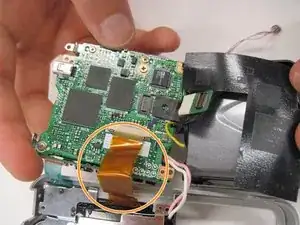
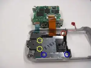
Detach the grey-capped wire found near the edge of the board.
-
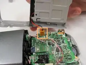
Located next to the blue wires is a green chip. Detach that green chip.
-
-
-
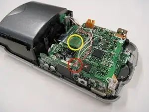
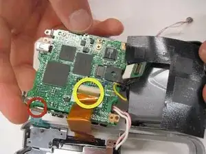
Remove the 3.5 mm screw that sits next to the rotating lens.
-
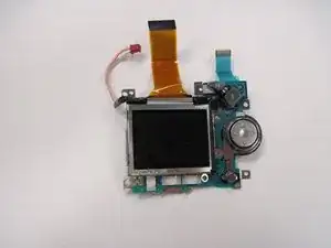
You will find that the motherboard is mobile. Flip, or invert the motherboard. Be cautious of the orange and blue ribbon cables. They should still connect the board to the LCD screen.
-
-
-
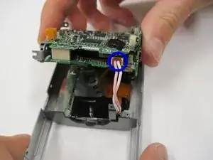
Detach the blue ribbon cable.
-
Using a spudger, detach the orange ribbon cable by pushing it out horizontally.
-
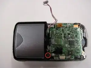
Detach the red-capped wire.
-
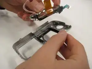
Lift the logic board and lens out of the back cover. Be sure that they are connected.
-
-
-
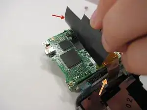
Lift the black covering
-
Remove the orange ribbon cable that connects the lens to the logic board.
-
To reassemble your device, follow these instructions in reverse order.