Introduzione
A broken LCD bracket could affect the placement of the LCD screen. This guide will show the replacement procedure for the LCD bracket. This guide also serves as a prerequisite for replacing the CCD sensor and the zoom lens unit.
Ricambi
-
-
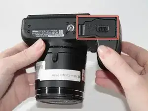
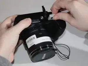
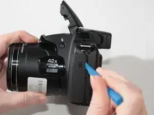
Slide the switch to the left to open the battery chamber using your fingertip or plastic opening tools.
-
The spring loaded battery chamber door will swing open after the switch is moved.
-
-
-
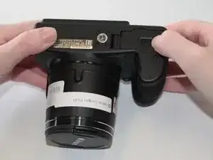
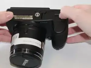
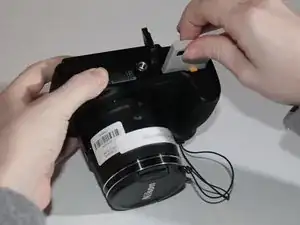
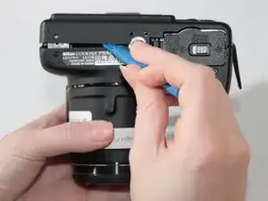
Depress the yellow spring loaded tab holding the battery in place using your fingertip or plastic opening tools.
-
After the yellow tab is depressed, the battery should partially eject from the camera.
-
-
-
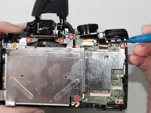
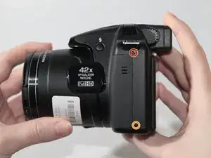
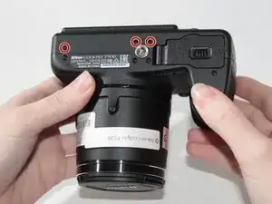
Remove the six 4mm screws highlighted in red with the Phillips #000 screwdriver.
-
Remove the 5mm screw highlighted in orange with the Phillips #000 screwdriver.
-
-
-
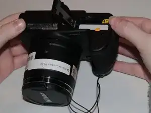
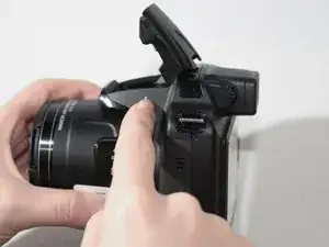
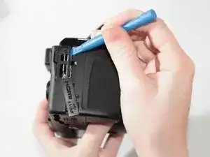
Pop up the camera flash using the button below the lightning bolt on the left side of the camera.
-
Identify the small notch below the camera flash where the body of the camera and the back cover join.
-
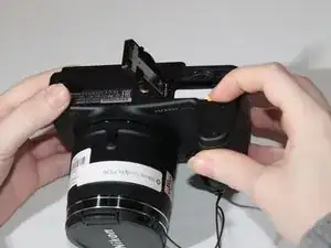
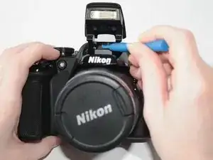
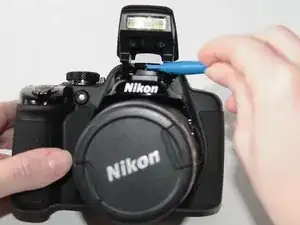
Use plastic opening tools to pry the darker plastic piece under the camera flash from the lighter plastic camera body.
-
-
-
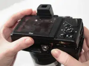
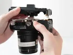
Gently lift the back cover away from the camera body.
-
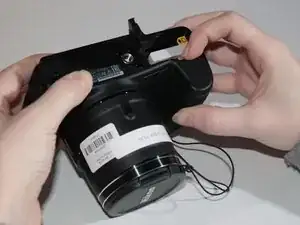
A gold ribbon cable will join the back cover of the camera to the internal electronic components. Be careful not to remove the back cover without removing the cable since this part can easily break.
-
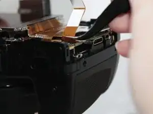
To remove the ribbon cable, gently pull the connector from the camera's internal electronic components using a pair of tweezers.
-
-
-
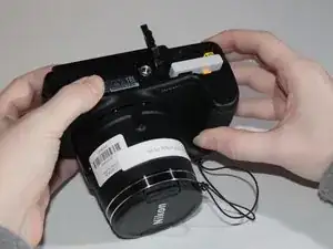
After the ribbon cable is removed from the camera body, the cover can be completely removed.
-
-
-
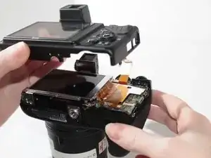
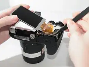
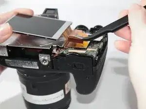
Tilt the screen towards the ribbon cable.
-
Remove the ribbon cable by gently pulling the cable away from the motherboard using tweezers.
-
-
-
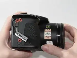
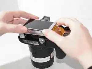
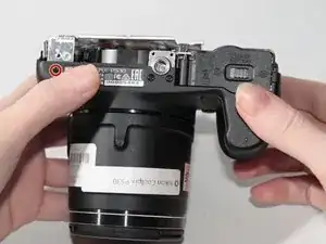
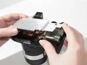
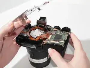
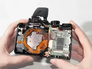
Remove the six 4mm screws highlighted in red using the Philips #000 screwdriver.
-
Remove the 6mm screw highlighted in orange using the Philips #000 screwdriver.
-

To reassemble your device, follow these instructions in reverse order.