Introduzione

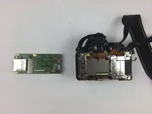
If your camera is malfunctioning or the external connection (micro USB and HDMI) ports are not working, then the camera's motherboard might be faulty and needs to be replaced. Before starting with this guide, refer to this troubleshooting page to check if there are any other possible causes.

  1. ORIEpLcOCJSoieeC
    • Use a Phillips #00 screwdriver for all of the screws.

    • Remove two of the 4mm screws indicated by the circles on the bottom side of the camera.

  2. rFCe6NYxdjQr5Slq
    rFCe6NYxdjQr5Slq
    XxW3pkWoDBKnvQar
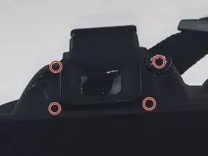
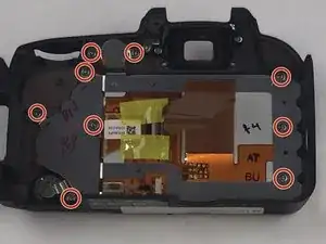
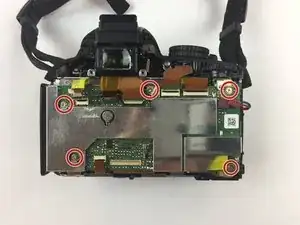
    • Remove four of the 3mm screws around the eye piece located on the top of the back panel, including the screw hidden behind the auto focus label.

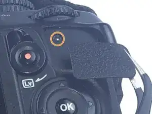
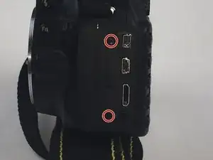
    • Remove the 3mm screw behind the rubber grip on the top right of the back panel.

    For my camera, the two bottom screws were 3mm, the upper left is 4 or 5mm, and the upper right (behind the label) is much larger.

    No problem, and they’re unambiguous

    Rob Cuthbertson -

  3. AtMTWR652Z6uRPKy
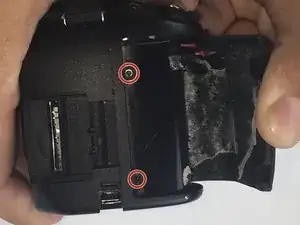
    • Peel back the rubber grip on the right side of the camera using a spudger.

    • You may need a heating pad to melt the glue holding the rubber grip to the camera. If using the heating pad, use caution and handle carefully.

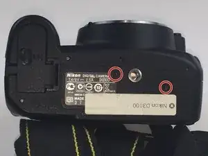
    • Remove two of the 5mm screws under the rubber grip.

  4. aEXaqV6eUufwMGwD
    • Remove two of the 4mm screws on the left side of the camera.

    You also have to remove the rubber cover for these ports, or you won’t be able to do the next step. Pull gently directly away from the camera body until the strap comes out. Re-insertion is as simple - push gently, or guide with a small flat-head screwdriver

    Rob Cuthbertson -

  5. BDI4cped5glJyinS
    BDI4cped5glJyinS
    KRLlowAQLMGIJrfD
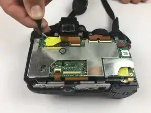
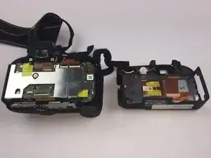
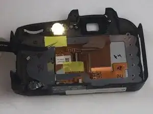
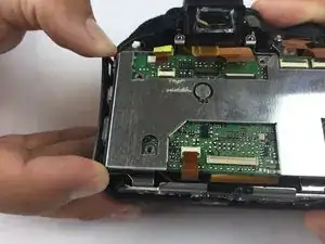
    • Starting from the top, gently lift the back panel of the camera off. Slowly separate the back panel from the main body of the camera.

    • Be careful not to pull the panel out too fast or the ribbon may be damaged.

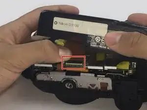
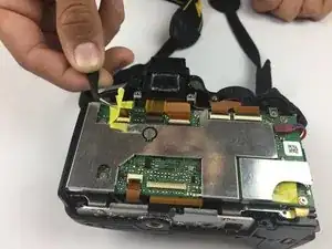
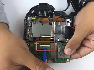
    • Carefully remove the ribbon using a spudger to lift up the connector and then use tweezers to pull out the ribbon.

    • Separate the back panel from the main body of the camera.

  6. BGfnl6HscSVuvJLm
    • Be careful when separating the metal plate from the back panel because the speaker wire is connected to the metal plate. It can easily be torn if caution is not taken.

    • Remove nine of the 3mm screws connecting the metal plate to the plastic panel.

  7. XoOrOtZouexLlKoZ
    • Remove the tape covering the ribbons. Be careful not to break the tape.

  8. GAMvUyOqKqOXn6Jn
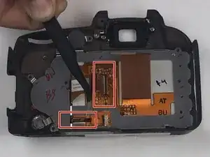
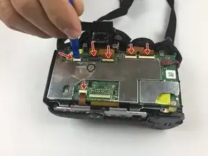
    • Remove the two ribbons connecting the LCD screen to the metal plate using the same method from Step 5.

  9. kS3nQXdITLVI6QEc
    • Remove the old LCD screen from metal plate.

  10. FGwCuJyjPirSBSKx
    FGwCuJyjPirSBSKx
    Rv1GgndS2sR6EvEZ
    • Use tweezers to gently lift the yellow tape from the back of the camera.

  11. YZJxjO4KJQwr46oD
    • Use a plastic spudger to remove the 6 ribbons.

    • Be careful not to tear the ribbons.

  12. iTSu2IXoD3TRnutQ
    iTSu2IXoD3TRnutQ
    ebBhlGtlYxsl1SAF
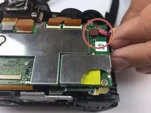
    • Remove the plug located on the top-right side of the camera.

    • Remove the plug located on the top-left side of the camera.

  13. RNUawTtTluiLFGnQ
    • Use a Philips #00 Screwdriver to remove the five 3 mm screws marked in the image.

  14. 5ay4qkEhPHxWTIiU
    5ay4qkEhPHxWTIiU
    EmOVf65b3T3Q5GfT
    • Gently pull out the side wall of the camera so that the motherboard comes out easier.

    • Do not pull too hard or you will risk breaking the plastic.

  15. Gp1kacCZ22rXDBfb
    • Be careful while lifting the motherboard because there is one more ribbon attached.

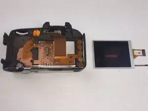
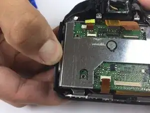
    • Gently lift the motherboard to separate it from the back of the camera.

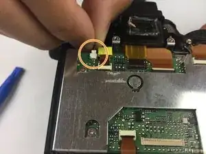
    • Use a plastic spudger to detach the ribbon.

  16. E23MQbUKHdEXXCKi
    • Replace the motherboard.

Conclusione

To reassemble your device, follow these instructions in reverse order.

Jet Mejia

Membro da: 26/09/16

606 Reputazione

0 commenti