Introduzione
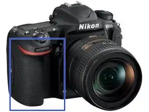
This is the steps to remove the top assembly of the camera.
-
-
Remove the Memory Card(s) from the camera
-
Remove the Battery from the Camera, and close the battery compartment cover
-
-
-
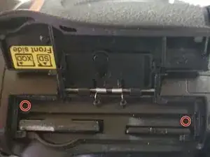
Remove the 2 screws beside the memory slots, then close the cover.
-
Note: make sure to remove the memory cards first!
-
-
-
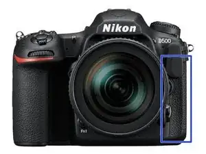
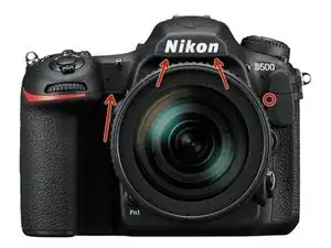
Remove the 2 screws under the rubber grip part by peeling back the rubber grip
-
Try not to damage the double sided adhesive under the rubber.
-
-
-
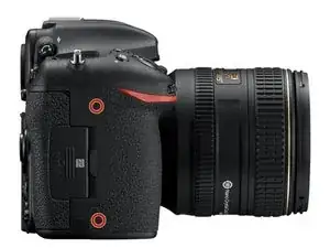
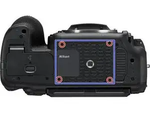
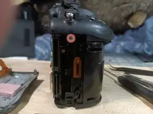
Remove the 2 screws under the rubber pad marked in red.
-
Try not to damage the double-sided adhesive under the rubber.
-
Note: There is a 3rd screw under the flap, which holds the back to the top (marked in yellow). If needing to remove the back panel not just the memory cover flap, it can be removed at this time as well.
-
-
-
Lift out the assembly panel, it should come free without much force.
-
May open the panel to release it.
-
-
-
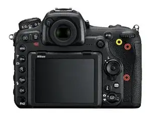
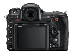
Carefully pull the back plate off the camera
-
There are 2 ribbon cables that need to be disconnected from the main board to free the rear panel from the camera.
-
To release the cables by flipping up the tap on the side away from the cable
-
When reconnecting the cables, make sure the cables are fully seated before flipping the latch back down.
-
The black cable goes to the LCD (on the tilt screen), the other one goes to the buttons.
-
The LCD cable does have less slack, so is easier to release first, and reconnect last.
-
-
-
Carefully remove the Rubber grip from the camera
-
Careful to not damage the double-sided adhesive
-
-
-
Carefully remove the Rubber grip from the camera
-
Careful to not damage the double-sided adhesive
-
-
-
Remove the diopter cap from the end of the diopter (use a flat head or pry tool)
-
Un-screw the phillips screw from the diopter
-
When reconnecting, make sure the cap is seated in correctly and the double sided tape is not damaged (or replace)
-
There is a notch which the indicator has to seat into, or it will not sit down correctly when it is reinstalled.
-
-
-
Remove the screw under the top assembly, had been hidden by the grip.
-
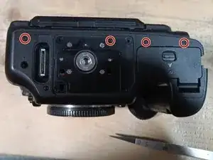
Remove the 2 screws from the bottom of the mirror box
-
Remove the lens or lenscap prior to doing this step to gain access, then reattach.
-
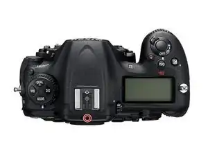
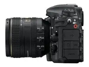
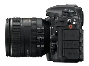
Remove the screw from beside the accessory socket
-
-
-
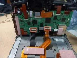
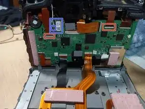
Disconnect the 2 ribbon cables from the main board (Red boxes)
-
Lift the black tabs above the cables to release the cables
-
When reseating the cables, make sure they are fully seated before closing the locking tab
-
Disconnect the wifi sub-board with the wifi cable from the main board (Blue Box) or gently disconnect the wifi antenna (Blue circle)
-
-
-
Carefully lift the top assembly free.
-
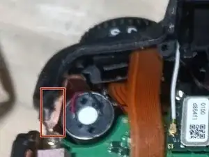
Note, there is a thermal pad on the left hand side, almost right under where the strap lug is. Red Box. Careful to not damage it.
-
To reassemble your device, follow these instructions in reverse order.
Careful of the thermal pad on the left side when placing the top assembly back onto the camera.
2 commenti
could you do a d5?
Yes, I could, if you provide me with a D5 to make the guide. :)
Wolphin -