Introduzione

Use this guide to replace the CCD sensor board.

  1. nGyLXbYAyfAxYqVM
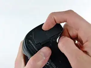
    • Use your finger tip to pull the battery release tab toward the center of the D70.

    • Open the battery door and rotate it away from the bottom cover.

  2. gP1L62ZOQKCETigP
    • Pull the battery out of the D70.

    • It may be necessary to wiggle the battery while pulling to free it from its pocket in the case.

  3. OnWdSq1ef45PHFXB
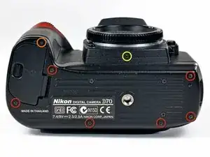
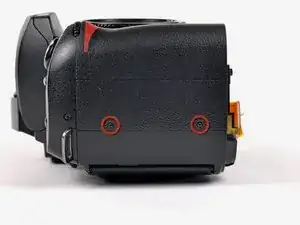
    • Remove the following eight screws securing the bottom cover to the D70:

    • Six 5.8 mm Phillips screws

    • One 10.7 mm Phillips screws

    • One 8.2 mm Phillips screws

  4. lQJ4MJE1bgjaNMlH
    lQJ4MJE1bgjaNMlH
    R4dLwLMcU1p52DrR
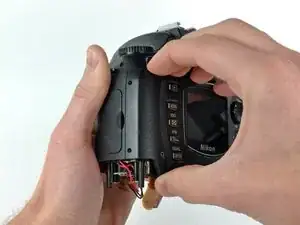
    • Carefully pull the bottom cover to separate it from the body of the D70.

    • Remove the bottom cover from the D70.

  5. P1ADOKYHItxyGnRG
    P1ADOKYHItxyGnRG
    q5RPJIPnUxTVXgSB
    BluG5IPJGpfVFA5u
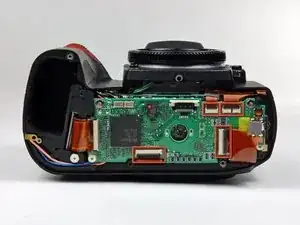
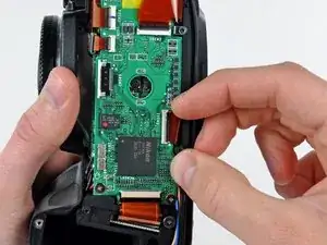
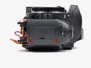
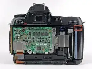
    • Remove the four ZIF ribbon cables highlighted in red by using the following procedure:

    • Use your fingernail to flip up the ZIF cable retaining flap on each socket.

    • Be sure you are prying up the retaining flap, not the socket.

    • Pull the ribbon cable straight out of its socket.

  6. Pd1Sb1dw1BMeuHLM
    • Carefully peel back the piece of tape covering the Compact Flash ribbon cable socket.

    • It is not necessary to completely remove this piece of tape.

  7. 1eItESfWWOSKpOID
    1eItESfWWOSKpOID
    COMQMkx4eO25tZVN
    VNxOgcCh6KuuEwMG
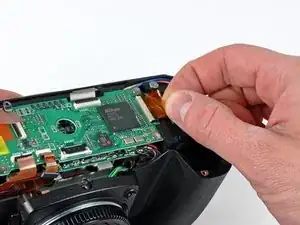
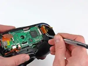
    • Use your fingernails to carefully pull the ZIF cable lock away from its socket.

    • Do not try to completely remove the ZIF cable lock. It will move about 1 mm and stop.

    • Use a pair of tweezers to pull the Compact Flash ribbon cable out of its socket.

  8. AdY1HaSiQD6O5ksm
    • Be sure not to lose the small iron core around the DC-In ribbon cable.

  9. qDOPPPYhtFjoJWWV
    • Remove the four 4.3 mm Phillips screws securing the memory compression board to the D70.

  10. BxibU1uHGmB2LPTO
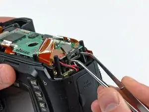
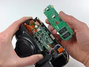
    • Use a pair of tweezers to pull the USB connector bracket away from the edge of the memory compression board.

  11. Rp334GYrORuBvtPd
    Rp334GYrORuBvtPd
    BZWCksZogQOe4pU4
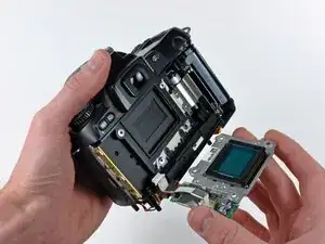
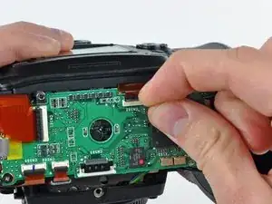
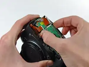
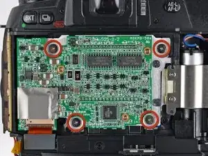
    • Grab the memory compression board by its edges at the position shown in the first picture.

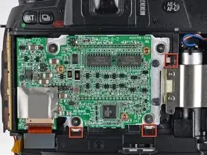
    • Pull the memory compression board straight up off the DC/DC board to avoid damaging the connector on the underside of the memory compression board.

  12. FsDYP2WIQHiTdZdv
    FsDYP2WIQHiTdZdv
    gTvHMBZxJsbathmg
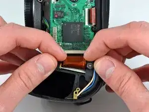
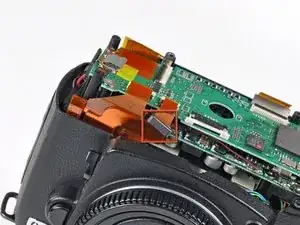
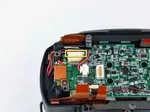
    • De-route the two leads routed over the connector boxed in yellow.

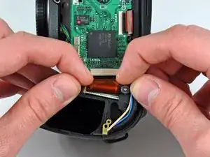
    • Use your thumbnails to push the connector out of its socket.

  13. 6MdZKn54PepMleVd
    • Remove the two Phillips screws securing the grip side of the rear cover to the D70.

  14. CsBugHvZQ3EOiH2S
    • Remove the two Phillips screws securing the DC-In side of the rear cover to the D70.

  15. rpPGuHlGPfPMdIFV
    rpPGuHlGPfPMdIFV
    pv5FWQY5vcmrrKGe
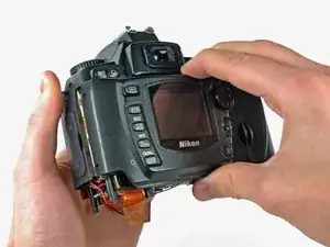
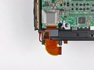
    • Carefully pull the sides of the rear cover away from the body of the D70.

    • Pull the rear cover off the body of the D70, minding the LCD board ribbon cable that may get caught.

  16. SWGGlR3U6RPNRPKn
    • At this point, the capacitor is visible and its exposed contacts are boxed in red. Even though they are recessed, be careful not to touch the contacts to avoid shocking yourself.

  17. qG1aZ25y4QO1Bow4
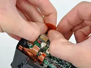
    • Peel back the piece of tape connecting the iron core around the CCD board ribbon cable to the inner case.

  18. dTK5ZVkAbPSuOeS2
    • Remove the four 4.8 mm Phillips screws securing the CCD board to the D70.

  19. ulZ6EMR1JesbtmWV
    ulZ6EMR1JesbtmWV
    4UF4GCJFkKvhShNt
    • Remove the CCD board from the D70, minding any cables that may get caught.

    • When reinstalling the CCD board, be sure to press the alignment posts on the right and bottom edges of the board up against the guides machined into the case while tightening the screws down.

Conclusione

To reassemble your device, follow these instructions in reverse order.

Andrew Bookholt

585555 Reputazione

2 commenti

Great instructions.

One important note: When re-installing the CCD board ribbon cable into the CCD board, the cable will go into the connector about 2mm and feel like it's seated. However, the cable must go 3mm-4mm into the connector. Otherwise, you will get a "This Card Cannot Be Used" error message each time you depress the shutter button.

Ross Edmond -

Great article.

davidmagen85 -