Introduzione
Use this guide to replace the memory compression board.
Strumenti
-
-
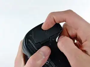
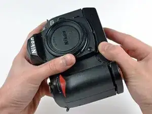
Use your finger tip to pull the battery release tab toward the center of the D70.
-
Open the battery door and rotate it away from the bottom cover.
-
-
-
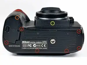
Remove the following eight screws securing the bottom cover to the D70:
-
Six 5.8 mm Phillips screws
-
One 10.7 mm Phillips screws
-
One 8.2 mm Phillips screws
-
-
-
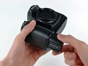
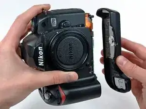
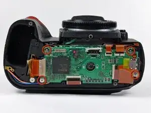
Carefully pull the bottom cover to separate it from the body of the D70.
-
Remove the bottom cover from the D70.
-
-
-
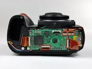
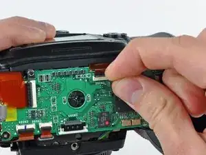
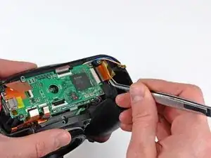
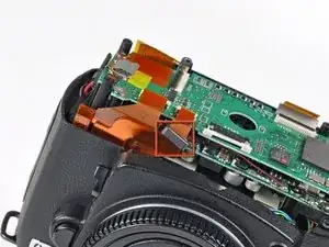
Remove the four ZIF ribbon cables highlighted in red by using the following procedure:
-
Use your fingernail to flip up the ZIF cable retaining flap on each socket.
-
Pull the ribbon cable straight out of its socket.
-
-
-
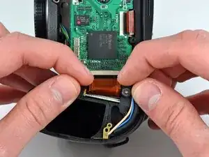
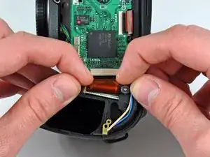
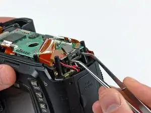
Use your fingernails to carefully pull the ZIF cable lock away from its socket.
-
Use a pair of tweezers to pull the Compact Flash ribbon cable out of its socket.
-
-
-
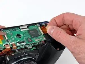
Use a pair of tweezers to pull the USB connector bracket away from the edge of the memory compression board.
-
-
-
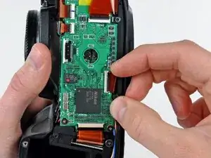
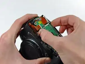
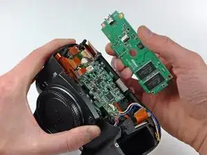
Grab the memory compression board by its edges at the position shown in the first picture.
-
Pull the memory compression board straight up off the DC/DC board to avoid damaging the connector on the underside of the memory compression board.
-
To reassemble your device, follow these instructions in reverse order.
