Introduzione
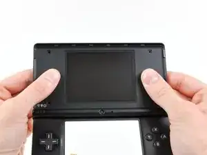
Use this guide to replace your DSi's dual cameras and their shared ribbon cable.
Ricambi
-
-
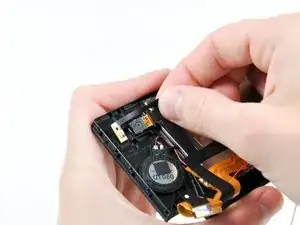
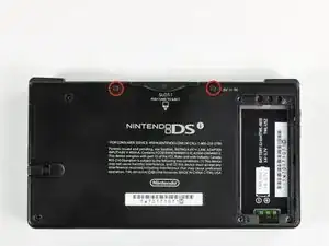
Unscrew the two Phillips screws securing the battery cover to the lower case.
-
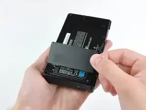
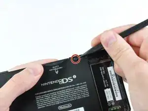
Grasp the battery cover and lift it out of the lower case.
-
-
-
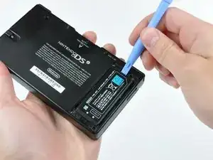
Using a spudger tool (or your fingernail), lift up the battery from the top.
-
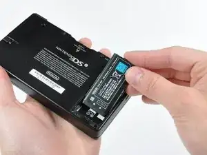
Grasp the battery and remove it from the DSi.
-
-
-
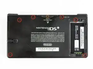
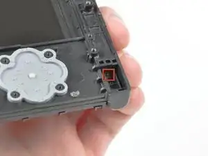
Two screws are hidden underneath two rubber feet highlighted in red.
-
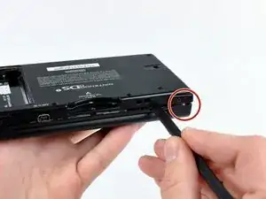
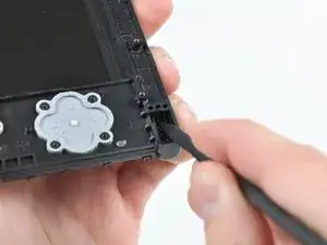
Use the tip of a spudger to pry the rubber feet out of the lower case.
-
-
-
Remove the following screws securing the lower case to the body of the DSi:
-
Six 5.2 mm Phillips #00 screws.
-
One 2.7 mm Phillips #00 screw.
-
-
-
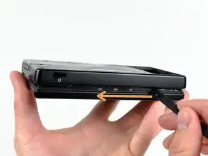
Insert the spudger in between the lower casing and lower panel near the top right corner of the DSi.
-
Carefully run the spudger along the edge of the outer casing, creating an opening between the body and the casing.
-
Continue running the spudger around the body of the DSi until the majority of the lower case has been separated.
-
-
-
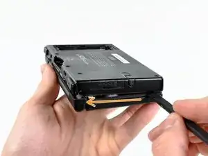
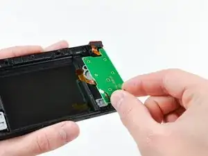
Carefully lift the lower casing from its bottom edge.
-
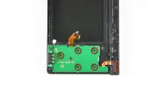
Pry the volume and SD board cable up from its socket on the motherboard using a spudger.
-
Once the cable is completely removed, then you may take off the entire outer casing.
-
-
-
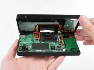
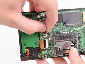
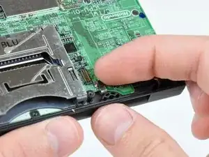
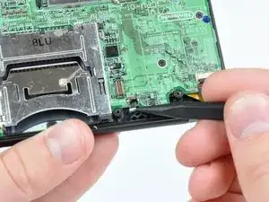
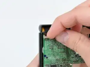
Use the tip of a spudger to pry the power board connector out of its socket on the motherboard.
-
-
-
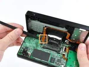
Use your fingernail or the edge of a plastic opening tool to flip up the retaining flap on the following three ZIF sockets:
-
Lower touchscreen cable
-
Lower LCD cable
-
Power board cable
-
After flipping up the locking tabs on all three sockets, use your fingers or a pair of tweezers to gently pull the cables straight out of their sockets.
-
-
-
Use your fingernail or the edge of a plastic opening tool to carefully flip up the touchscreen ribbon cable retaining flap.
-
Use the tip of a spudger to pull the touchscreen ribbon cable straight out of its socket.
-
-
-
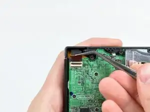
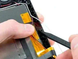
Use your fingernail or the edge of a plastic opening tool to carefully flip up the dual camera ribbon cable retaining flap.
-
Use the tip of a spudger to pull the dual camera ribbon cable straight out of its socket.
-
-
-
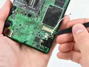
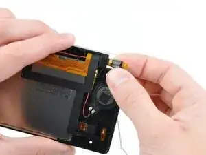
With the tip of a spudger, Pry the microphone antenna up off its socket on the motherboard.
-
-
-
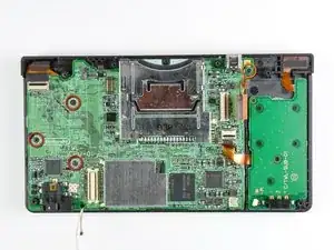
Remove the following four Phillips screws securing the motherboard to the DSi framework.
-
Three longer screws.
-
One short screw.
-
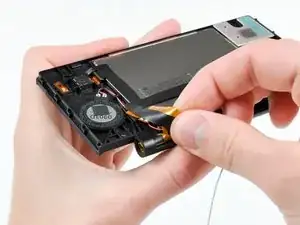
Pull the microphone and Wi-Fi antenna cables out of the notch cut into the motherboard near the headphone jack.
-
-
-
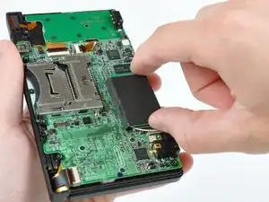
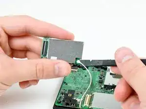
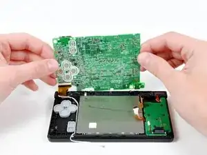
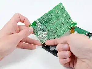
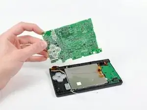
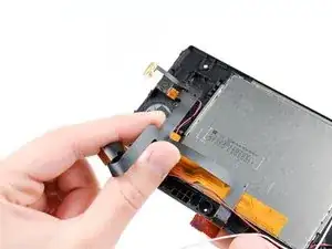
Slightly lift the motherboard upwards to reveal the upper LCD ribbon cable above the ABXY buttons .
-
Use your fingernail or the edge of a plastic opening tool to carefully flip up the upper LCD ribbon cable retaining flap.
-
Remove the motherboard from the DSi.
-
-
-
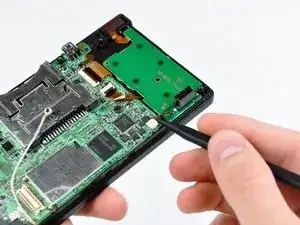
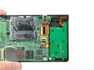
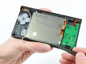
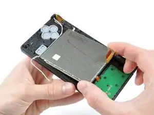
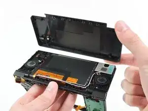
Use the tip of a spudger to pry the metal backing of the lower LCD up from the DSi's framework.
-
Lift the lower LCD assembly out of the DSi.
-
-
-
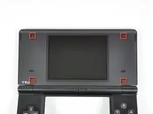
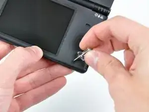
Use a pushpin to remove the four plastic screw covers (highlighted in red) on the front bezel.
-
-
-
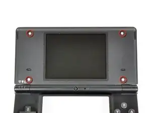
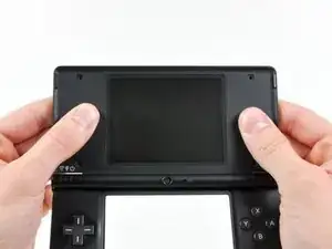
Using two hands, gently slide the rear bezel upwards.
-
Lift the rear bezel straight up out of the DSi.
-
-
-
De-route the microphone and Wi-Fi antenna cables through the opening located on the bottom DSi's framework.
-
-
-
Remove the five Phillips screws securing the power board to the DSi's framework.
-
Lift and remove the power board from the DSi.
-
-
-
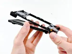
Push the metal hinge pin inward on the D-pad side of the front lower panel with the tip of a spudger.
-
The pin should move about 3 mm and stop. It is not necessary to try to completely remove the pin.
-
-
-
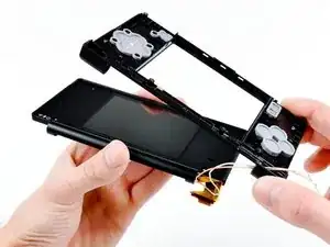
Slightly detach the lower and upper halves of the DSi.
-
De-route the upper LCD and dual camera ribbon cables through the slit near the ABXY side of the front lower panel.
-
Separate the lower and upper halves from each other.
-
-
-
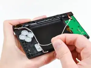
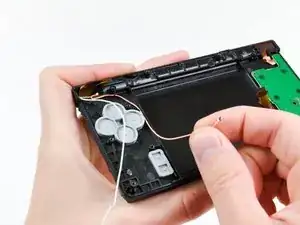
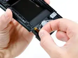
Using your fingers, grasp the microphone cable and remove it from the front bezel assembly.
-
The microphone will likely pop out of its housing, so it is probably easier to completely remove it at this point.
-
De-route the Wi-Fi antenna cable through the hinge.
-
-
-
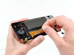
Tightly coil the display and dual camera ribbon cables enough to push them through the steel hinge tube.
-
Remove the steel hinge tube.
-
Carefully push both coiled ribbon cables through the tube molded into the front upper panel.
-
-
-
Lift the rear-facing out of its housing in the front bezel.
-
Remove the dual camera cable assembly from the DSi.
-


To reassemble your device, follow these instructions in reverse order.
