Introduzione

Use this guide to replace the three status LEDs on the hinge of your DSi.

  1. xvUu2VHXnLOaoxyD
    xvUu2VHXnLOaoxyD
    GJgBKkUY2j6UrTTr
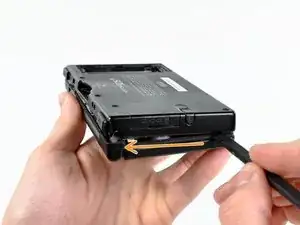
    • Unscrew the two Phillips screws securing the battery cover to the lower case.

    • The screws remain captive to the battery cover.

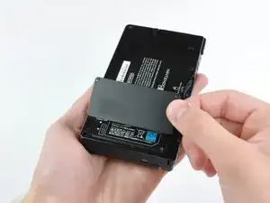
    • Grasp the battery cover and lift it out of the lower case.

    • If it's difficult to grasp, lightly tap the opposite side of the device.

  2. TMGAeGDWRXJKjqkf
    TMGAeGDWRXJKjqkf
    pXTJP3k1hRhVckSv
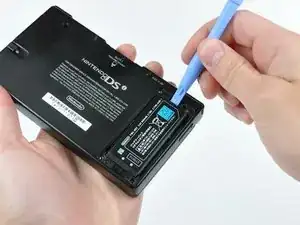
    • Using a spudger tool (or your fingernail), lift up the battery from the top.

    • The liquid damage indicator sits underneath the battery. Pry gently, or you may damage the indicator.

    • There's a small tab on the top of the battery to make removal easier.

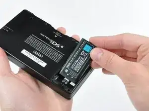
    • Grasp the battery and remove it from the DSi.

    This is also where the water damage indicator is located, if that's important

    [REDACTED] -

  3. ZElvjs4G5DRnVKEX
    ZElvjs4G5DRnVKEX
    NNd3fYSswNeKCoBU
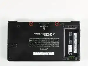
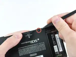
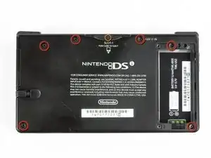
    • Two screws are hidden underneath two rubber feet highlighted in red.

    • Use the tip of a spudger to pry the rubber feet out of the lower case.

    One of the feet did break on me, tweezers came in handy for picking it out

    Willie Narvaez -

    I unfolded and sharpened a paperclip. You can use that to stab and hook the rubber without tearing it, as the rubber is thick enough to reseal when reinserted.

    Keegan Andersen -

    Nasty, broke my spudger and the feet in this step.

    TimedIn -

  4. MPpnnO22qoYDH1YH
    • Remove the following screws securing the lower case to the body of the DSi:

    • Six 5.2 mm Phillips #00 screws.

    • One 2.7 mm Phillips #00 screw.

    Impossible d'enlever les vises… trop serré! comment faire?

    evrobert03 -

    i can't get the screw by the gamecard slot out, PH#00 is too small and PH#0 is too big

    Iblowup -

    same problem here. maybe try a JIS?

    darth mango -

  5. MqTKErbDcomH6eMJ
    MqTKErbDcomH6eMJ
    HuePUMK6TciCQZEj
    OkwvvvtBbd53ugBG
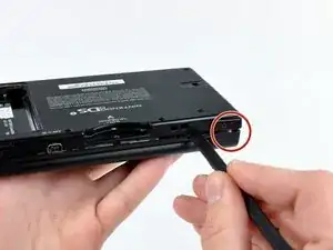
    • Insert the spudger in between the lower casing and lower panel near the top right corner of the DSi.

    • Carefully run the spudger along the edge of the outer casing, creating an opening between the body and the casing.

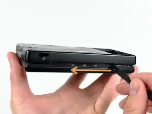
    • Continue running the spudger around the body of the DSi until the majority of the lower case has been separated.

  6. ZsX1F2YxXpOFEtuH
    ZsX1F2YxXpOFEtuH
    BS25HSFVrSclu2X1
    • Carefully lift the lower casing from its bottom edge.

    • The lower case is still attached to the motherboard by the volume and SD board cable highlighted in red. Do not try to completely remove the lower case of the DSi yet.

    • Pry the volume and SD board cable up from its socket on the motherboard using a spudger.

    • Once the cable is completely removed, then you may take off the entire outer casing.

  7. 1ypLDSJeLf3Ej1sW
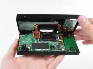
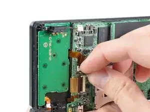
    • Use the tip of a spudger to pry the power board connector out of its socket on the motherboard.

    I broke my white box off the wires and off the mother board. Please help.

    Jack Meloche -

  8. aycKuTuwUnxBQvJ2
    aycKuTuwUnxBQvJ2
    xRkZIsUutnebm2bN
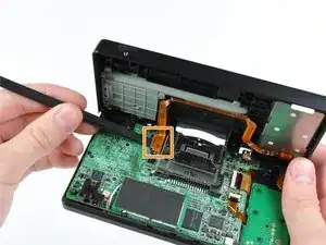
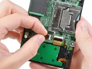
    • Use your fingernail or the edge of a plastic opening tool to flip up the retaining flap on power board ZIF connector.

    • Be sure you are prying up on the hinged retaining flap, not the socket itself.

    • After flipping up the locking tab on the socket, use your fingers or a pair of tweezers to gently pull the cable straight out of its socket.

  9. AhULZToBwiNCM5lD
    AhULZToBwiNCM5lD
    MmS5WR4lpXsIPywl
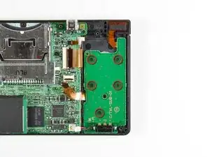
    • Remove the five 2.6 mm Phillips screws securing the power board to the DSi's framework.

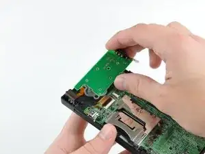
    • Lift and remove the power board out of the DSi.

  10. HVrabaS5vyXHkpXS
    HVrabaS5vyXHkpXS
    aYnBTRaaQeEnAnQa
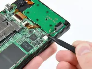
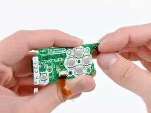
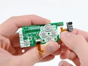
    • Use your fingernail or the edge of a plastic opening tool to flip up the retaining flap on LED indicator ZIF connector.

    • Be sure you are prying up on the hinged retaining flap, not the socket itself.

    • After flipping up the locking tab on the socket, use your fingers or a pair of tweezers to gently pull the cable straight out of its socket.

    • If necessary, transfer the power board ribbon cable to your new power board.

  11. DhNEnUZF6QbL3lWR
    • LED indicator board remains.

Conclusione

To reassemble your device, follow these instructions in reverse order.

Andrew Bookholt

585555 Reputazione

0 commenti