Introduzione
This guide will help removed and replaced your damaged or old motherboard. If you have problems turning on your camera and you have checked your battery then you may need to follow this guide to replace the motherboard. Before you begin, make sure that the battery and SD card have been removed.
-
-
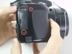
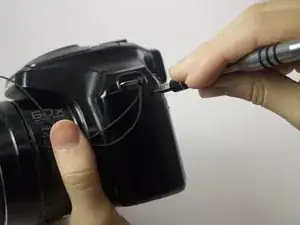
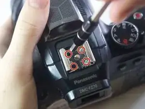
Using your screwdriver, unscrew the two 5.0 mm Philips screws to the right of the LCD screen.
-
-
-
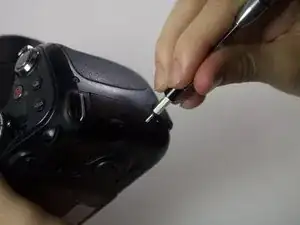
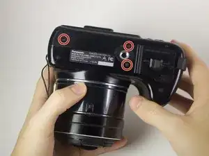
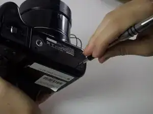
Flip the camera over to the left side of the screen and unscrew the 5mm Phillips screw found there.
-
-
-
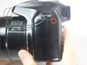
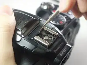
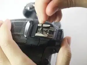
On the top of the camera locate the two rails with a thin sheet of metal on the floor between them.
-
With a metal spudger, lift this sheet and push it out of the rail device to detach it from the camera.
-
-
-
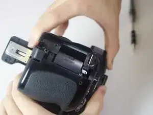
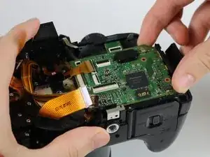
Slowly pull on both side of the camera, until both halves begin to separate from each other.
-
-
-
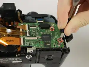
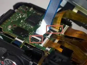
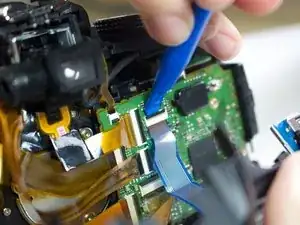
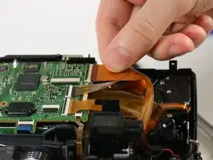
Using a plastic opening tool, carefully flip up the small black levers that attach the ribbon cables to the ZIF connectors on the motherboard.
-
Carefully pull the ribbon cables out of the slot once they have been released.
-
-
-
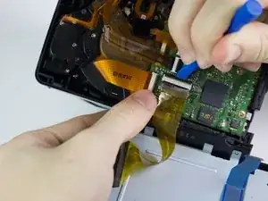
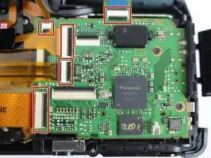
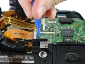
The five ribbon cables shown will need to be removed from the ZIF connectors. Using a plastic opening tool, unlock the cables by lifting the black strip on the rectangular connection socket.
-
Carefully pull each of the ribbon cables out of their sockets.
-
-
-
Once the screws and the ribbon cables have been removed, lift the mother board from its slot.
-
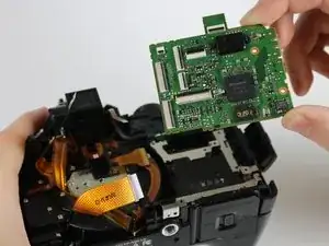
To reassemble your device, follow these instructions in reverse order.