Introduzione
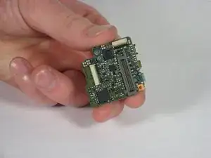
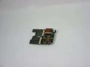
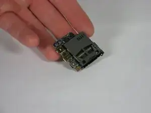
This is the circuit board that the AV chord attaches to for transferring images.
Strumenti
-
-
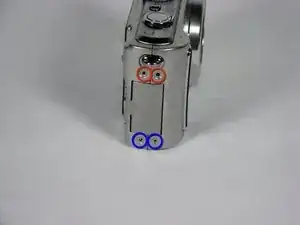
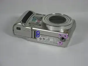
Remove 4 screws from the right side of the camera.
-
There are two 3.4mm screws at the top.
-
There are two 2.2mm screws at the bottom.
-
-
-
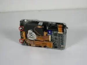
Remove 5 screws from the base of the camera.
-
There are two 2.2mm screws next to the battery compartment.
-
There are three 4mm screws around the tripod mount.
-
-
-
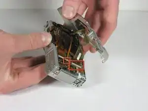
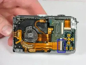
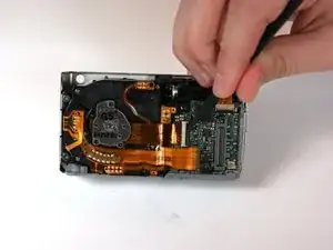
Detach both ribbon cables using a spudger.
-
Use the tip of the spudger to lift the black clip upward, unlocking the ribbon cable.
-
-
-
Use the spudger to remove the ribbon cable connecting the lens casing to the circuit board by lifting up the black clip.
-
Carefully remove the function switch cover. This unit snaps on and off.
-
-
-
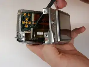
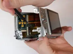
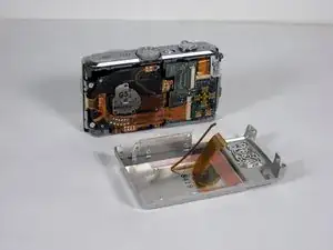
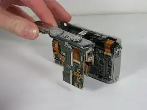
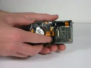
Slide the entire top part of the camera that is attached to the logic board, horizontally away from the camera.
-
-
-
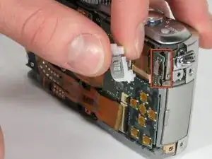
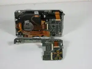
Remove the ribbon cable from the top connection panel by unlocking the black clip with a spudger.
-
This leaves you with the logic board and the top connection panel separate and free from the camera
-
-
-
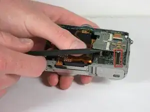
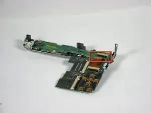
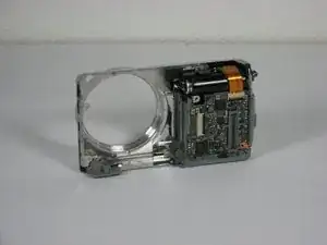
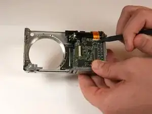
Use a spudger to detach the ribbon cable from the circuit board. Lift the black clip up to unlock it as before.
-
-
-
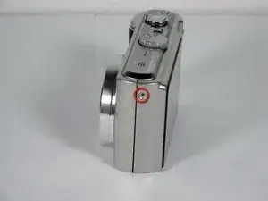
Remove the 3 screws holding the lens assembly in place.
-
The two screws on the left are 4.5mm with washers.
-
The single screw on the right is 4mm.
-
-
-
Push the lens assembly slightly toward the circuit board, and pull the left side out of the casing first. You will have to wiggle this out gently.
-
-
-
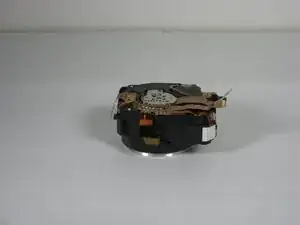
Remove the entire assembly out of the casing.
-
The ribbons on the left and bottom of the assembly simply rest on the camera housing.
-
-
-
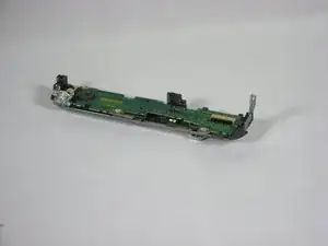
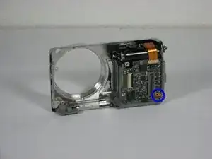
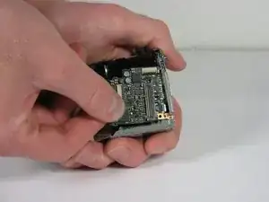
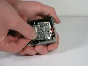
Gently slide the circuit board out away from the port connections. Pull it toward where the lens used to be. Some wiggling may be necessary to remove.
-
To reassemble your device, follow these instructions in reverse order.
Un commento
Where can I buy this part? Thanks!
Janx38 -