Introduzione
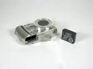
This guide is for replacing the entire camera lens assembly. It will guide you through all of the necessary steps to disassemble your camera.
Dissasembly of the lens box is not documented here and involves complex gear matching.
Strumenti
-
-
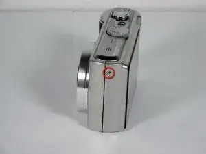
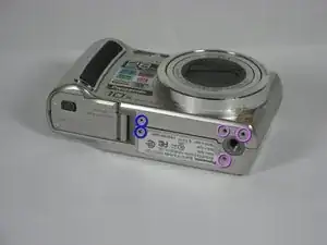
Remove 4 screws from the right side of the camera.
-
There are two 3.4mm screws at the top.
-
There are two 2.2mm screws at the bottom.
-
-
-
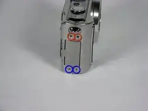
Remove 5 screws from the base of the camera.
-
There are two 2.2mm screws next to the battery compartment.
-
There are three 4mm screws around the tripod mount.
-
-
-
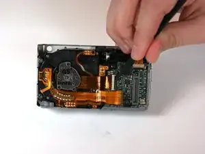
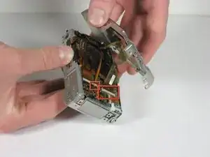
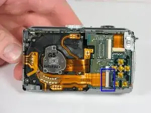
Detach both ribbon cables using a spudger.
-
Use the tip of the spudger to lift the black clip upward, unlocking the ribbon cable.
-
-
-
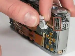
Use the spudger to remove the ribbon cable connecting the lens casing to the circuit board by lifting up the black clip.
-
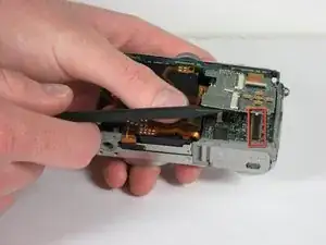
Carefully remove the function switch cover. This unit snaps on and off.
-
-
-
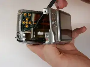
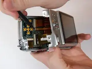
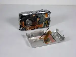
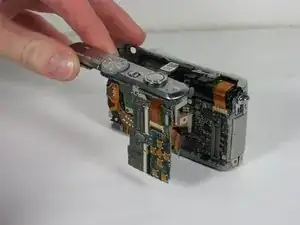
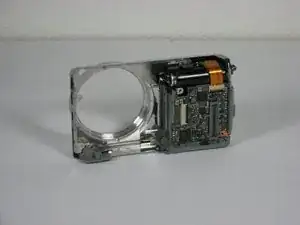
Slide the entire top part of the camera that is attached to the logic board, horizontally away from the camera.
-
-
-
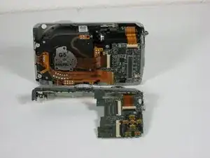
Remove the ribbon cable from the top connection panel by unlocking the black clip with a spudger.
-
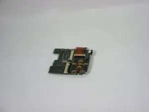
This leaves you with the logic board and the top connection panel separate and free from the camera
-
-
-
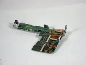
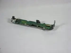
Use a spudger to detach the ribbon cable from the circuit board. Lift the black clip up to unlock it as before.
-
-
-
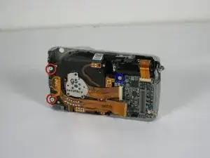
Remove the 3 screws holding the lens assembly in place.
-
The two screws on the left are 4.5mm with washers.
-
The single screw on the right is 4mm.
-
-
-
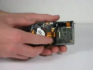
Push the lens assembly slightly toward the circuit board, and pull the left side out of the casing first. You will have to wiggle this out gently.
-
-
-
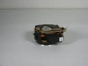
Remove the entire assembly out of the casing.
-
The ribbons on the left and bottom of the assembly simply rest on the camera housing.
-
To reassemble your device, follow these instructions in reverse order.
Un commento
I have a Lumix, not sure if it is this one, but I now have a MUCH better idea on how to proceed. I was knocked off a shelf(in case) and fell about five feet to the floor. Dang CAT! It powers on and (if I recall) will still capture an image but the display is simply white. This tells me most of the camera is functioning and the ribbon cable has become disconnected.(I hope)
I have looked for this info before and have no idea why it did not show up on DDG, Google, or SP. Thank you for this guide.
T Bob Trasman