Introduzione
This guide will provide you with step-by-step help for replacing the flash unit of the Pentax Optio WP Digital Camera.
Strumenti
-
-
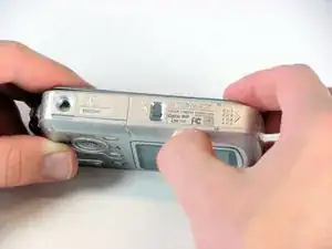
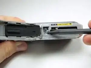
Orient the camera so you are looking at the bottom and the battery compartment is on the right hand side.
-
-
-
Unlock the battery compartment by sliding the lock switch to the unlock position (away from the arrow).
-
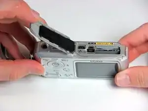
Firmly push the battery cover to the right and swing open.
-
The battery will be located in the larger bottom slot. Slide the plastic orange tab to remove the battery.
-
The SD card will be located in the smaller, top slot. Push the SD card directly in to hear a small clicking sound. Then pull out the SD card.
-
-
-
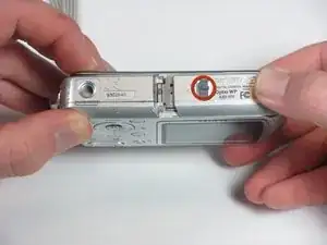
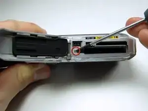
With the battery cover swung open, use the spudger to remove the DC IN sticker.
-
Remove the 4.3 mm silver screw revealed.
-
-
-
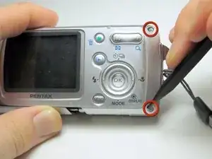
Reorient the camera so it is upright and you are looking at the back screen.
-
Remove the rubber covers in the upper and lower right side corners. Insert spudger in between the camera case and the rubber cover and push them out of their sockets. Grab the rubbers with the tweezers and set them aside. Remove both of the 4.3 mm silver screws revealed.
-
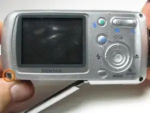
Remove the 4.3 mm silver screw in the lower left corner which resides under the sliding battery cover.
-
-
-
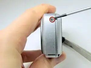
Locate the 5.3mm silver screw on the edge closest to the upper left corner of the LCD screen and remove it.
-
-
-
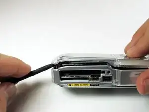
With the spudger, pry back the cover starting with the outer edge to release.
-
Detach the copper ribbon from the internals of the camera by placing a finger on top of the terminal and gently pulling on the back casing.
-
-
-
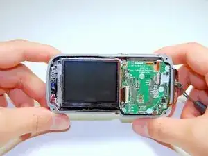
Orient the camera so you are looking at the LCD screen.
-
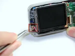
Using the forceps, remove the red and white wires out of the terminal in the bottom left corner.
-
-
-
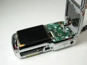
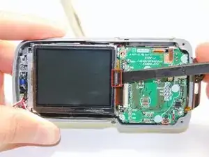
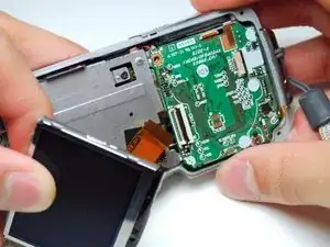
Remove the LCD screen from the camera by inserting the spudger between the screen and the metal hook on the right side of the screen and prying up gently.
-
Flip open the black gate holding the copper ribbon from the LCD screen.
-
-
-
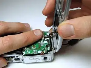
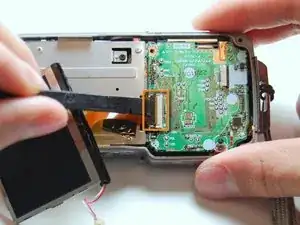
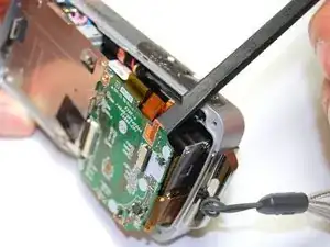
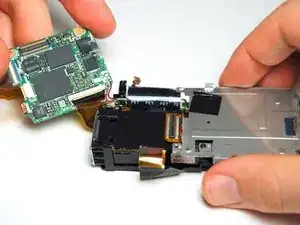
Carefully pry the electronic internals out of the front casing with the spudger.
-
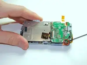
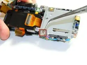
With tweezers, carefully detach the ribbon on the upper right corner of the internals that is connected to the shutter release/power button.
-
-
-
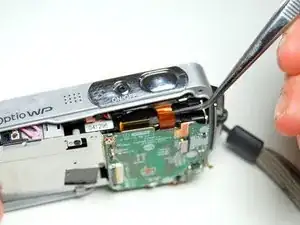
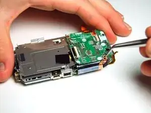
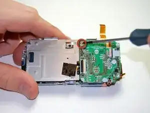
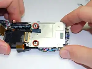
With the tweezers, carefully peel back the copper ribbon that was underneath the black screw.
-
-
-
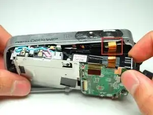
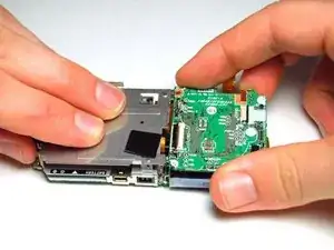
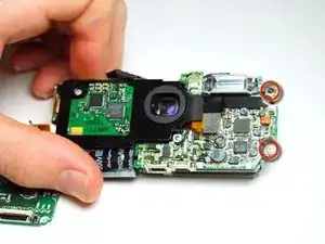
Press down on the metal plate and gently lift the motherboard up from left to right.
-
Reorient the camera so you are looking at the top edge with the metal plate on the right.
-
-
-
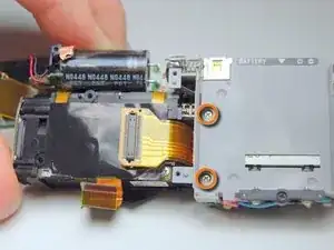
Peel back the black plastic revealed under the LCD screen on the metal plate.
-
Remove the two 4.3 mm black screws on the left edge of the metal plate.
-
-
-
Reorient the camera so you are looking at the front with the lens in the upright position.
-
Remove the 4.3 mm black screw in the upper right hand side of the camera as well as the 4.3 mm silver screw in the lower right hand side of the camera.
-
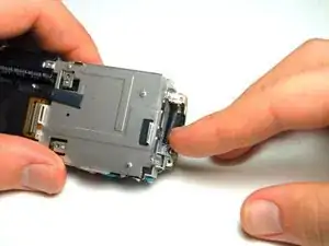
Reorient the camera so you are looking at the back with the metal plate on the right side.
-
-
-
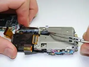
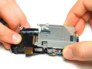
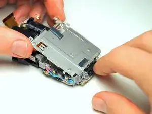
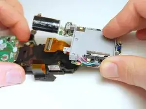
While holding down the black plastic on the right edge of the metal plate, pry the plate up and to the right until it is completely vertical.
-
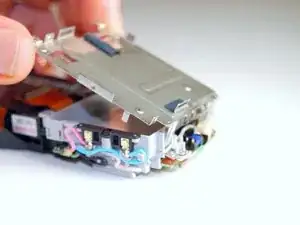
Lift the metal plate straight up to remove it.
-
-
-
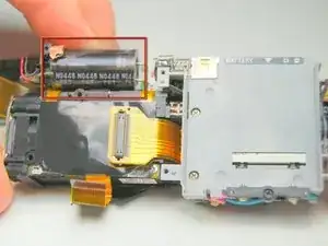
With the tweezers, remove the spring on the bottom edge of the battery compartment.
-
Remove the two 4.3 mm silver screws on the inside of this compartment.
-
Lift and remove the flash unit from the left side of the assembly.
-
To reassemble your device, follow these instructions in reverse order.