Introduzione

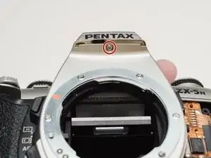
A common failure of the Pentax ZX-5n is the Mirror Drive Lever. This is a plastic lever on the side of the mirror box that moves the mirror up and down during an exposure. The plastic tip that follows the rotating cam can break off leaving the mirror stuck in the up position. The shutter should still fire normally but the mirror won't travel its full stroke. Additionally, with the mirror stuck, the viewfinder will appear black and the camera will not be able to autofocus.

This guide explains how to disassemble the camera to access the Mirror Drive Lever as well as how to install the new part to ensure proper functionality. A general understanding of how cameras work is recommended. Some technical soldering is also required.

  1. lgs2BFmwctNUvEEY
    • Push down on the screw to depress the spring loaded hinge and release the door.

  2. xqMOa4QfTrEMSjLQ
    • Remove six 5.3 mm #00 screws.

    • Remove one 3.4 mm #00 screw.

    • The short screw has a machine thread and screws into the plate underneath. The rest screw into the plastic body.

  3. JBNm1gvrrVIsOnvC
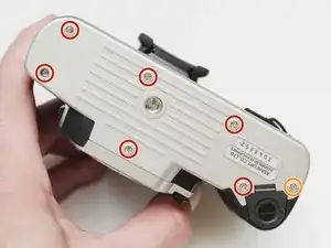
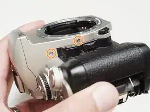
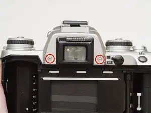
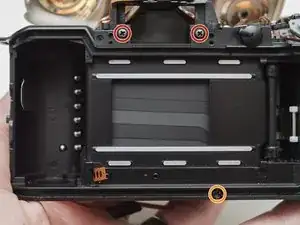
    • Remove three 5.3 mm #00 screws (the bottom-most screw is not always present).

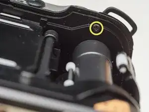
    • Remove one 7.3 mm #00 screw.

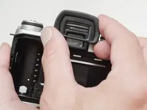
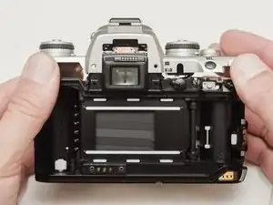
    • Remove the remote trigger cover.

  4. kaurbKcGc3sICMvp
    kaurbKcGc3sICMvp
    qAMWaUYPEdKSqKBQ
    • Remove one 3.4 mm #00 screw.

    • Remove two 5.3 mm #00 screw.

    • Gently lift up on the flash housing to help remove the cover if necessary.

  5. XTT2gETZspMWvdLW
    • Remove two 3.9 mm #00 screws.

  6. 3my2vQuEkTFMiy1K
    • Slide the eye cup up and off to access the screws underneath.

  7. e53TOwaDpAgeyAD6
    e53TOwaDpAgeyAD6
    OJJ5WDhEjPdLrFAa
    XYapgMENQtcSAZZH
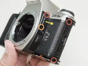
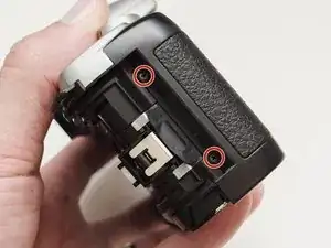
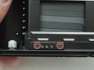
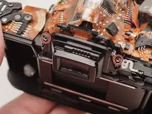
    • Remove two 5.3 mm #00 screws by the eyepiece.

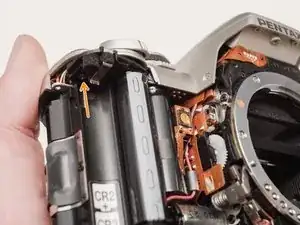
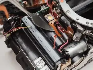
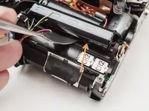
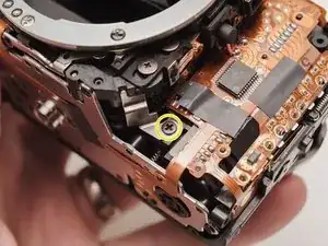
    • Remove one 6.8 mm #00 screw in the battery compartment.

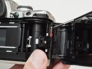
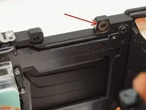
    • Remove one 7.0 mm #00 screw near the take up spool.

  8. htpX4AygbXbvTyuw
    • Lift the cover so it is just free of the body. It is still attached by several wires.

  9. EFlKCVmvVgDDLxaG
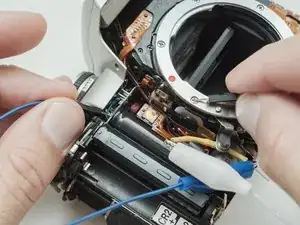
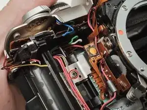
    • Use a 1kΩ-10kΩ resistor to discharge the capacitor. Place the resistor between the blue wire, exposed in the previous step, and ground.

    • The flash capacitors store energy at a very high voltage. Failing to discharge the capacitors properly could result in personal injury and/or damage to the camera.

    My camera doesn't have the same yellow connection point (is it apart of the camera or your own). I was wondering if there was any other way to discharge the flash capacitors? And how do I know when I've completed the step, any sound cue? Thanks in advance.

    tarek tarek -

    The yellow piece you see in the picture is a resistor covered in heat shrink tubing. When you discharge the capacitors, you are making a connection between the high voltage pin and ground, which allow the energy to flow out. The resistor is there to slow the current and have a safer discharge. If you don't have a resistor in the range listed, picking something higher will still allow a safe discharge but it will take longer. With a 10 kOhm resistor, it usually takes about 10 seconds to fully discharge. I check the voltage with a meter to make sure it's at a safe level. There isn't really an audible or visual cue to know whether it has discharged.

    Sam Gustafson -

  10. WFylZB5bMqTOGvD4
    • De-solder the green, blue, brown and black wires from the flash PCB.

    When soldering the connections, what temperature would you recommend?

    tarek tarek -

    I'm not sure what the optimal temperature is. My soldering iron is set at 380 C but that might be a little on the high side.

    Sam Gustafson -

  11. HOKWLOh2yNg6DQZL
    HOKWLOh2yNg6DQZL
    ga2UdqOFAj3PiPot
    jlANcHMqBCEjTIhY
    • Move the top cover to the side to access the battery connections. It is still connected by a flex cable.

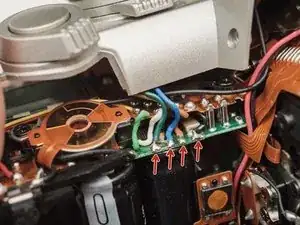
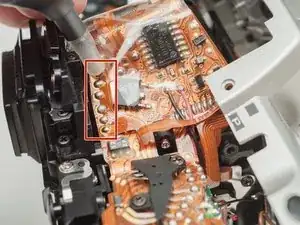
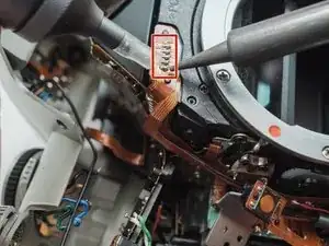
    • De-solder the indicated joints. Use a solder sucker on the tabbed connections.

    • Pull the black wire from the battery flex to get more slack in the connection to the top cover.

    • Be careful not to overheat the flex circuit. Work in short durations. Allow for cool downs in between if necessary.

  12. VwsRACw1G3GIsVfd
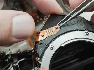
    • Desolder the flex cable connecting the top plate to the camera body.

    • Be careful not to overheat the flex circuit. Work in short durations. Allow for cool downs in between if necessary.

    • The top cover can be completely removed at this point.

  13. ywWMNUNRinvtxUBv
    • Use a solder sucker to de-solder the four posts from the flex circuit.

    • This is the most difficult part of the repair. Patience and persistence are required.

    • Be careful not to overheat the flex circuit. Work in short durations. Allow for cool downs in between if necessary.

  14. cwTT1OO3NASdSWar
    • De-solder the marked connections.

    • Be careful not to overheat the flex circuit. Work in short durations. Allow for cool downs in between if necessary.

  15. N2ZakjMEIJ4uPcEx
    • Remove one 4.3 mm #00 screw.

  16. BJWKBkWKOX3LNEXa
    BJWKBkWKOX3LNEXa
    iUKQN4JxkMihbEHH
    • Gently pry up the plastic carrier under the flex circuit. It may catch slightly on the battery contact tab.

    • Pay close attention to the connections around the four through-hole posts as you lift the flex. Make sure that no solder is left over and that it pulls away freely.

    • This metal tab is lightly held in place with lacquer and can easily come loose. Keep an eye on it.

  17. rW36Nytm5MX4ypxw
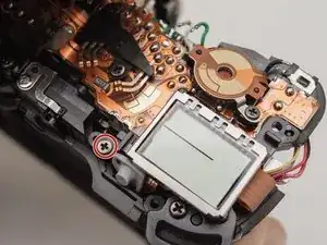
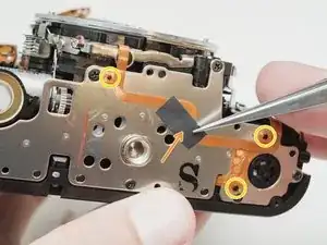
    • Remove one 3.3mm #00 screw.

    • Remove one 3.9 #00 screw.

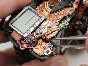
    • De-solder the red wire.

    • Peel off the black tape. Leave it attached to the wires.

  18. RW4tpsArJ2gxXCJF
    RW4tpsArJ2gxXCJF
    ZVd5QUYQqYSrQWBb
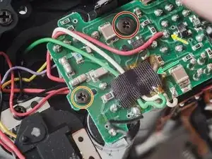
    • Gently peel the flex circuit from the surface of the capacitor.

    • There may be additional adhesive underneath the larger capacitor.

    • Lift the two capacitors and the flash PCB out as a single unit.

    • The double sided tape used to secure the capacitors can be softened with isopropyl alcohol if necessary.

  19. PKWDKajPwI1IsKvN
    PKWDKajPwI1IsKvN
    UBHqaljejtUWVWKI
    • Remove two 3.4 mm #00 screws. Remove the plate holding the contacts in place.

    • Peel tape from the plate. Leave the tape attached to the flex circuit.

    • Remove the flex circuits from their retaining studs.

  20. uykjwxRmjoOdsLBL
    uykjwxRmjoOdsLBL
    IQuZFa2eCtcwCXYD
    • Remove one 3.3 mm #0 countersunk screw.

    • Remove one 3.9 mm #0 shoulder screw.

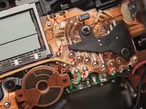
    • Remove four 3.3 mm #00 screws.

    • Pull a little slack through the housing on this flex cable.

    • Pop the plate off its posts, rotate slightly clockwise and pull gently through the loosened flex cable.

    • To the camera tech that left me a happy little note...I see you.

  21. vKTVsERkAFutSugF
    vKTVsERkAFutSugF
    HncNyUpLEDnLUcwx
    • It's best to remove these parts now so they don't fall out later on in the repair.

  22. BukgOTmEoQwjJVK2
    • Remove one 3.8 mm #00 screw.

  23. 6EJUQtJirvXIbsrO
    6EJUQtJirvXIbsrO
    w6SkTQDnJYYn6nQM
    • De-solder the connections.

    • Lift the flex off the retaining studs.

    • Be careful not to overheat the flex circuit. Work in short durations. Allow for cool downs in between if necessary.

  24. GWbVit2G2EaIBZrF
    • Remove two 5.3 mm #0 screws.

  25. nBISUVwyL41GLgdn
    nBISUVwyL41GLgdn
    CvgtCljeqsoJ2nom
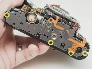
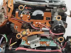
    • Remove two 7.4 mm #0 screws.

    • Remove one 8.3 mm #0 screw.

    • Remove one 3.3 mm #00 screw. The metal bracket will be loose and should be removed as well.

  26. LAgMTSDFMK55Mn66
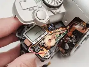
    • Push the front housing block slightly up then lift the left side up and away from the housing.

    • Proceed slowly and watch for any components that are catching. The right side is still attached by a large flex cable.

  27. sqLIcBJXpDWvMoVB
    • There may be shims at the mounting points of the front housing block.

    • Note the positions and remove if loose.

  28. xU5SQbKRBCij3T3J
    xU5SQbKRBCij3T3J
    ovj23pDEeystPliS
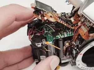
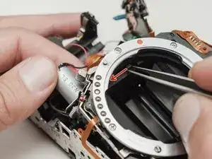
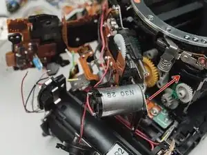
    • De-solder the black wire.

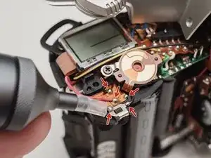
    • Remove four 3.7 mm #00 screws.

    • Detach the buzzer from its mounting posts. Use isopropyl alcohol to soften the lacquer if necessary.

  29. ZYctoPbqVAQynFcB
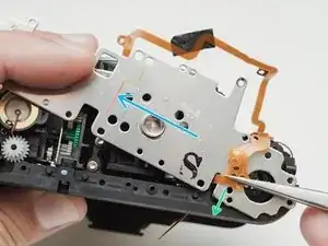
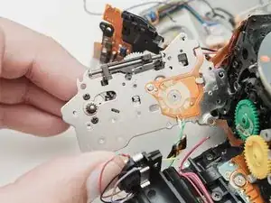
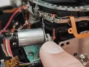
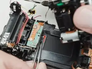
    • Grab the motor and gently wiggle the plate loose.

    • If it feels stuck, move the sliding plate down, towards the bottom of the camera

  30. hSgehwcJS2uPdX3l
    • Slide the green and yellow gears off of their shafts.

  31. qEYGoMEDBDleED6a
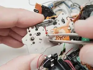
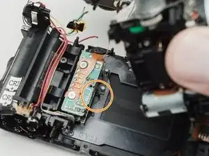
    • The broken part. If the small tip is completely detached, locate it and remove it from the camera before reassembly.

    • Place a finger over the larger spring to keep it in place as you slide off the lever.

  32. DRHLtCsDYTHwnbHB
    DRHLtCsDYTHwnbHB
    SwMAQ45pkGNmeHNl
    • Use tweezers to place the spring arm on the lower side of the post and tension the lever.

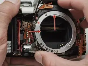
    • Place the long spring arm on the left side of the mirror pivot.

    • Check proper function of the mirror by moving the bottom arm of the lever back and forth. The mirror should rest in the upper position but be able to move up and down.

    • If using a 3D printed replacement part, remove the tensioning spring and temporarily install the green gear Turn it counterclockwise through the entire mirror cycle. There should be no binding of the gear at any point. Adjust the drive lever as necessary until it moves through the entire cycle without resistance.

  33. 54AFfqx2fZRoqHr2
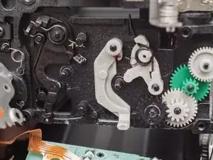
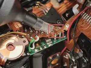
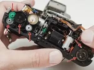
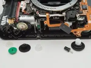
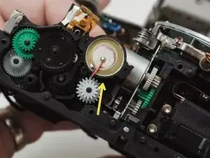
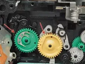
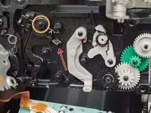
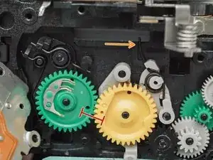
    • When placing the gears, line up the two indicated holes. The gears must be in sync for the shutter and mirror to work properly.

    • Turn them back and forth a few degrees to make sure they are fully seated.

    • Aperture set lever spring. Note this part for installation of the mirror motor assembly.

  34. qdfoeSQqAPpmRt4J
    qdfoeSQqAPpmRt4J
    ZkawTBF4thbuOfMT
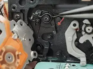
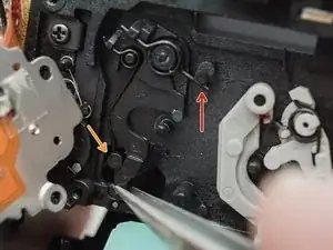
    • Disengage latch so the slide bar can move freely.

    • Move the slide bar about half way down its total travel.

    • Let the latch snap back into place so the slide bar is held in the new position.

    • This ensures that the aperture set lever spring couples properly with the slide bar during reassembly.

  35. DxihsJkBJHbCqmbe
    • Place the left side first. Then swing the right side in, coming up and under the spring loaded lens release.

  36. LdXSyM2QAuytxkgU
    • Rotate the grey gear downward until the mirror is in the charged/down position.

  37. wg3tIV4DHaP6FMVb
    wg3tIV4DHaP6FMVb
    sKCPobXJqIlAVJ12
    • Push the shutter charge lever upward. You should see the shutter blades move as you do this.

    • The second picture shows the shutter in the charged position. It may already be in this position and not need charging.

    • Gently place the front assembly block. Work it into place until the back of the block is flush to the back of camera.

    • Proceed with the rest of the re-assembly, following the guide in reverse.

Conclusione

To reassemble your device, follow these instructions in reverse order. Pay attention to the wire routing as you re-solder connections. They need to be in the correct places to install the body covers.

Sam Gustafson

Membro da: 02/09/22

3233 Reputazione

0 commenti