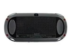
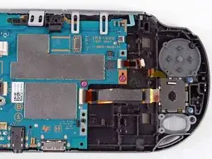
Introduzione

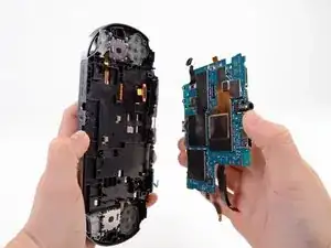
This guide takes you through the process of installing the motherboard.

  1. bXHPdJvmOqwnRZ5W
    bXHPdJvmOqwnRZ5W
    Kxh4sK2xMaaiHQtJ
    • Power off and remove the memory card.

    • Using a Phillips #00 screwdriver, remove the four 6.4mm screws on the back casing.

  2. WwpKNcKBHnx3iwJP
    WwpKNcKBHnx3iwJP
    36FYDevnAqBvbNY3
    mjh2iFATaa2BKMEs
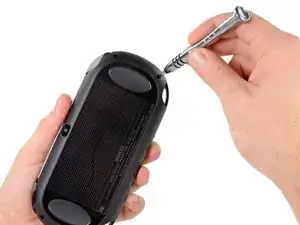
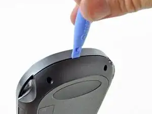
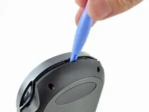
    • Using your fingernail or a spudger, pry open the accessory port cover on the top of the device.

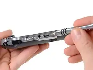
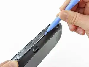
    • Using a Phillips #00 screwdriver, remove the two 5.4mm screws hidden beneath the accessory port cover.

  3. AH6yWSkBJ4VWv3RB
    AH6yWSkBJ4VWv3RB
    aXih4BBWrQN2fmOK
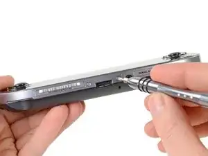
    • Remove the two 5.4mm Phillips #00 screws on the bottom of the device near the charging port.

  4. bEJVmiEky4mHiDcb
    bEJVmiEky4mHiDcb
    aQOOn4pkOrVFR3hw
    vEQhcA4OEHFKVYLS
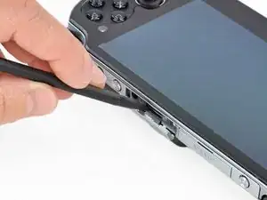
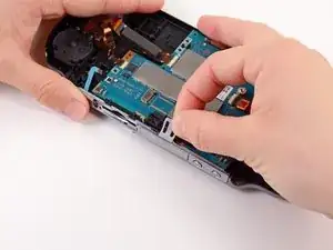
    • Beginning at the sides of the device, use a plastic opening tool to separate the front and rear cases.

    • Continue working your way around the device gently prying it open.

    • There are still wires holding the front and rear cases together. You may damage the connections if you yank the cases completely apart.

  5. 3BBZJmwmjKVUDiJa
    3BBZJmwmjKVUDiJa
    EpjUlyY4L4GWcaLS
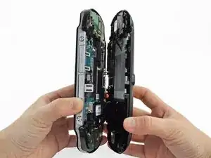
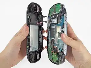
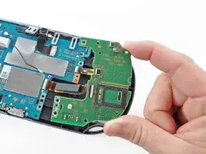
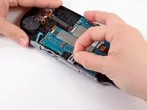
    • Gently separate the two cases, minding the battery and the touch screen controller connectors holding the two cases together.

    One of the shoulder buttons fell out when I was doing this step, along with the piece holding it in place. They go back in just fine when reassembling but make sure that they are oriented properly, of course.

    klung -

  6. NeowybD4slFqYmiM
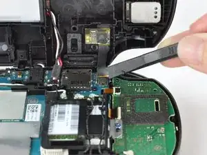
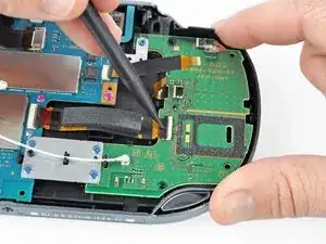
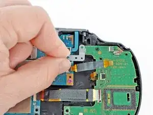
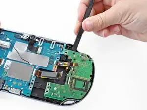
    • Using a spudger, free the touch screen controller flex cable by gently prying up the connection.

  7. DtebpV1FIAkm4AUj
    • Free the battery cable by gently prying up on the connection with a spudger.

    Any idea what type of pcb header is on the board for the battery? I have a motherboard with a broken header but I cant source a replacement

    Jimbo Jones -

    This is where I screwed up so I recommend extra caution for other newbies. Only the black part is supposed to come off. Don't be an idiot like me and pry off too much...

    ylimakiminna -

    Yea I messed up there too. Is there a way to fix it?

    Alethia Henry -

    This component was far more stubborn than the screen connector when it came to removal. I opted for a smaller tool than the spudger (small flat-head) and managed to disconnect it after determining the best bit size for the job. Screwdriver is metal, obviously, so being gentle helps to avoid damaging anything.

    klung -

    broke the white part

    Benaya Miller -

  8. fkyIaVUrPDRIlhZV
    • Separate the front and rear cases.

  9. vlXZZ4MfiNjWSFqf
    vlXZZ4MfiNjWSFqf
    sQ1gbc2E5BkZFX2R
    1HAJbEsQW1AOGbmI
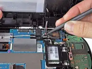
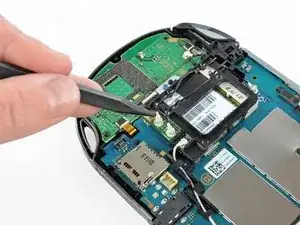
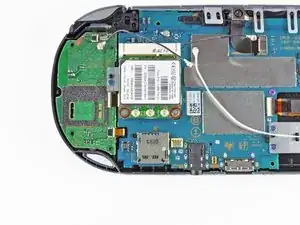
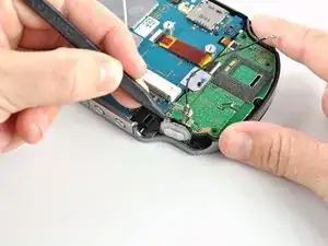
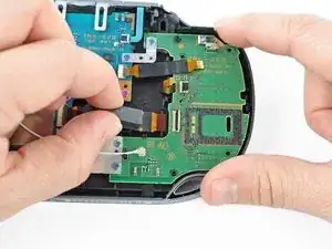
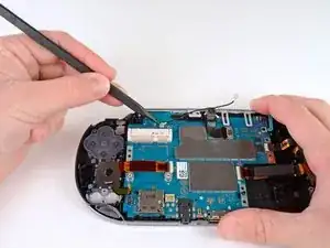
    • Using the pointy end of the spudger, disconnect the three antenna cable connectors on top of the wireless card.

    • Deroute the antenna cables so that they are out of the wireless card casing. Rest the wires out of the way.

    Step 9-11 only apply to the 3G version of the PS Vita.

    logicj83 -

    Hello, I have the PCH-2001 model of the PS vita and the right analog stick went out. I ordered a replacement and the stick is slightly larger than the original. The original has a black rectangle on the back, the new version has the star version, which is what you have on this website as the replacement part. Any help here would be much appreciated. Thanks.

    Ben Ragains -

    Can I install a WiFi motherboard on a 3g ps vita model 1100?

    fmind11 -

  10. yKBmQZ5D12sRhGXX
    yKBmQZ5D12sRhGXX
    JH6WVtknwNbxKhD5
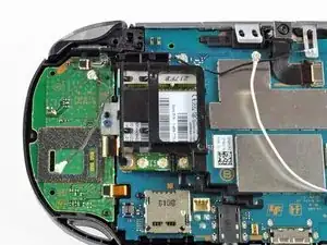
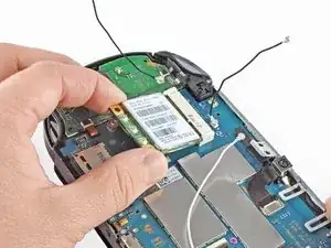
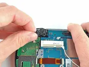
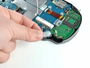
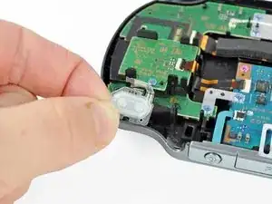
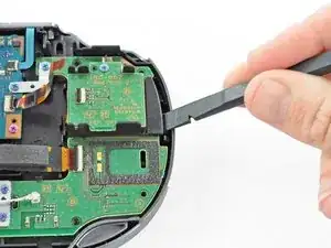
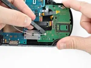
    • Hook the spudger beneath the tab on the wireless card casing and release the tab.

    • Peel up and remove the wireless card casing.

  11. JutjPPe6MLOg26PI
    JutjPPe6MLOg26PI
    jerqgQIbknJfbPur
    • Remove the two 4.4mm Phillips #00 screws on the wireless card.

    • The wireless card will naturally pop out at an angle.

    • Pull out the wireless card.

    My screwdriver does not want to unscrew those. They won’t turn at all.

    Rei -

    My screwdriver does not want to unscrew those. They won’t turn at all.

    Got the same, used PH #0 and grabbed wireless card casing with fingers from the top to release pressure on screen and avoid (possibly) breaking it.

    Yuriy Zhyromskiy -

    Some PS vita models seem to use a T2 screw instead of a PH#00. I’ve encountered this twice now.

    kaosjr kaosjr -

    I replaced de wifi card but is still difficult to connect to wifi. Could it be the wifi antenna? which cable model is it?

    Fernando Diaz -

    3G Vita 1000.

    I found that the PH00 head wouldn't actually fit in to the screw correctly. A PH000 fit but was still requiring a bit more force than seemed necessary. Also the card did not pop up when the screws were released and that's because Sony used a tacky pad under the card so needed a bit of prying up to get the angle.

    Paul Pimm -

  12. LFlqLFyOWenu3flq
    LFlqLFyOWenu3flq
    XA3ULsGnxwM1dCqJ
    IwHAvTU2HypmMy4M
    • Pry up the right shoulder button casing with a spudger and set it aside.

    Is this really necessary?

    fmind11 -

  13. OaUrqnJngB4x3kSs
    • Remove the translucent, plastic right shoulder button cover.

  14. DBAvdSFGaDNWgCoP
    DBAvdSFGaDNWgCoP
    qRv22Bsq3VvEXFRX
    lZIfHy3s4oM2VAQq
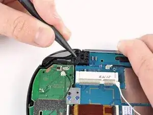
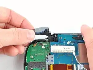
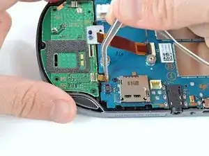
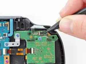
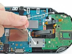
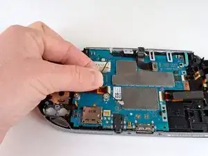
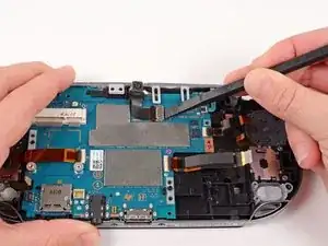
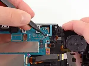
    • Release the right shoulder button flex cable socket by using a spudger to gently pry open the tab.

    • Using tweezers, slide the flex cable out of the socket.

  15. PA2LCk4SImWo1gbk
    PA2LCk4SImWo1gbk
    dxeEBBsrHTOGZLJK
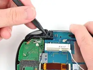
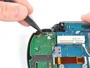
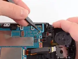
    • Using a spudger, gently peel up the right shoulder button from the light adhesive connecting it to casing.

  16. ItTaPwOhLVLOhDRY
    ItTaPwOhLVLOhDRY
    fKSLp2GxUOfUQvOU
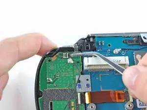
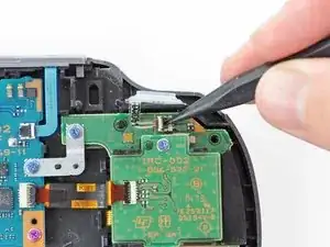
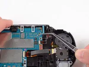
    • Using the pointy end of a spudger, detach the antenna cable on the right button board.

    • Remove the antenna cable.

  17. lBKNRO1MO2ljUWbw
    lBKNRO1MO2ljUWbw
    TILjfuGxlKAhSZ6G
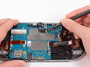
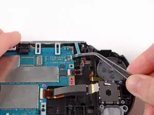
    • Using a spudger, pry up and release the ZIF socket on the right button board.

    • Gently pull the flex cable out of the socket. Rest the flex cable out of the way.

  18. 4BkulyBveDCRaEc2
    4BkulyBveDCRaEc2
    PD6Oam1isGJWxl3r
    dHT2IZH3gOSStJKa
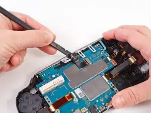
    • Release the tab on the small flex cable socket by prying up the tab with a spudger.

    • Using tweezers, gently pull the flex cable out of the socket. Rest the flex cable out of the way.

  19. D2Q1HXSElH21eJDI
    D2Q1HXSElH21eJDI
    QvKXPYOlC2WSRHSn
    lOPJHyLupOQLCRpk
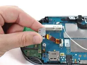
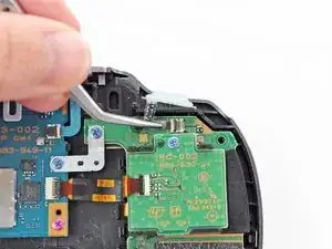
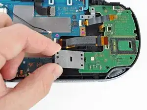
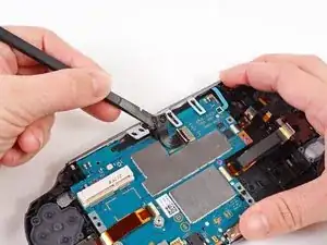
    • Remove the two 5.0mm Phillips #00 screws from the metal bracket securing the right button board to the motherboard.

    • Remove the metal bracket, using a spudger as necessary to lift it out.

  20. ySuNwUCsUMGFMGLR
    ySuNwUCsUMGFMGLR
    1AZ1PntbCEX1CMxp
    YJUCkFhenb42g4XM
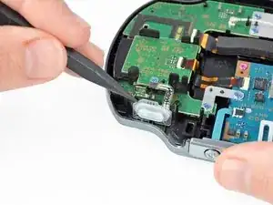
    • Use a spudger to free the right button board by prying up from the bottom right corner of board.

    • Gently lift the right button board out.

  21. EEmLIrKv4dHKsk1j
    EEmLIrKv4dHKsk1j
    1pQo3KjHMVBOVnBC
    I2JYMM1x2igll1I1
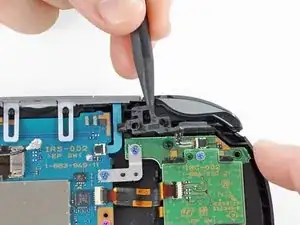
    • Pry up the left shoulder button casing with a spudger.

    • Remove the left shoulder button casing.

  22. LrALDSbuNdoHWTZe
    LrALDSbuNdoHWTZe
    nDZW2JWWsSyM5MXI
    • Remove the translucent, plastic left shoulder button cover.

  23. vpbObMcWUOMII432
    vpbObMcWUOMII432
    TbWqrYJPpsZJkeYf
    NMMqqFH2OmGJK1jZ
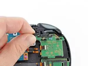
    • Release the left shoulder button flex cable socket by using a spudger to pry open the tab.

    • Be careful to not break off this small black tab!

    • Using tweezers, slide the flex cable out of the socket. Do not pull on the black tab! Instead, pull the thin flex cable away from the connector (to the left in this image).

    broke the small black tab, what happens if I just go without it??

    Nicolas Porfirio -

  24. EuVHYx1UjbOAl4pq
    EuVHYx1UjbOAl4pq
    FHMI5vnO6qVuOuL6
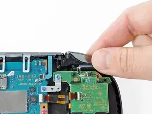
    • Using a spudger, gently peel up the left shoulder button from the light adhesive connecting it to casing.

    This step is unneccesary.

    Alexander Mayatsky -

  25. ReaLF5hNnDtB4hGY
    ReaLF5hNnDtB4hGY
    5VUcvMNLhHaOZQWv
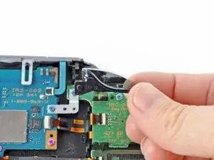
    • Using a spudger, lift and release the tab on the ZIF socket sitting on the SIM card reader.

    • Carefully pull the flex cable out of the ZIF socket, and rest it out of the way.

    Este paso NO es necesario si tu PSVita no tiene lector de tarjeta SIM. Ve directamente al paso 15.

    Parappa The Rapper -

  26. GrmEMEJIsv2VIsIY
    GrmEMEJIsv2VIsIY
    5gSGRVqGG3JHFJS6
    TjKFsL3RdxsmR6ae
    • Use a spudger to release the tab between the SIM card reader and the back casing assembly.

    • Lift the SIM card reader off the back casing assembly.

    This board is not present in the Wifi only version, only the 3G/Wifi version.

    dodo -

  27. uhrPkiflxnJg1x1K
    uhrPkiflxnJg1x1K
    X4mQUe2LLVeVBTM2
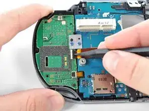
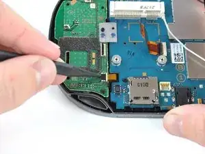
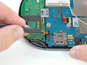
    • Release the plastic tab on the small flex cable socket by prying it up with a spudger.

    • Using tweezers, gently remove the small flex cable from the socket, and rest it out of the way.

  28. WQtNPDCbJhAFdhqf
    WQtNPDCbJhAFdhqf
    WJxCqSV5w2cyrrSd
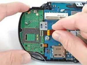
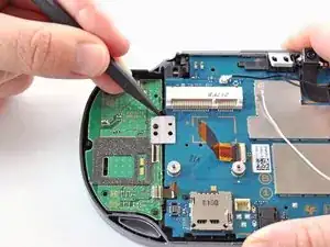
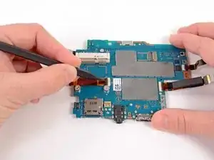
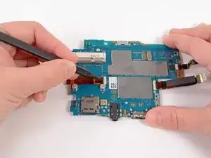
    • Use a spudger to lift up the tab on the large ZIF socket.

    • Gently pull the flex cable out of the ZIF socket, and rest it out of the way.

  29. 1IvJRIjs2t2Ufwng
    1IvJRIjs2t2Ufwng
    lOPyuvpuHacqOKkC
    • Disconnect the white Wi-Fi antenna cable with a spudger.

    • Remove the Wi-Fi antenna cable.

    This connector isn't present in the Wifi only version, just the 3G/Wifi version.

    dodo -

  30. xSVxNWXXTUQvjnVx
    xSVxNWXXTUQvjnVx
    45TZfQiLNuShS2bB
    PZurSbIvaKUM5RZo
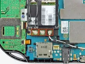
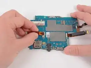
    • Using a Phillips #00 screwdriver, remove the six screws on the two metal brackets:

    • Two 5.0mm, blue screws on the L-bracket securing the upper left button board to the motherboard.

    • Four 5.0mm, blue screws on the square bracket securing the lower left button board to the motherboard.

    What is the loose looking cable in this photo?

    Dallon Verhaeghe -

  31. jGlIgvoCnMQ5bla5
    jGlIgvoCnMQ5bla5
    sxyVEpnrjHWjEFyc
    FGXIOZ3D5s3Zu6PX
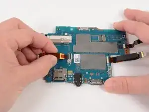
    • Starting from the upper left corner, use a spudger to pry up and remove the left button board.

  32. XPtDRb3UDjLHfxjl
    XPtDRb3UDjLHfxjl
    XR6YaB5OWKbtAhB3
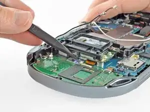
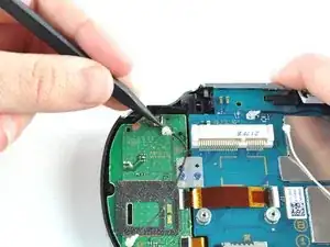
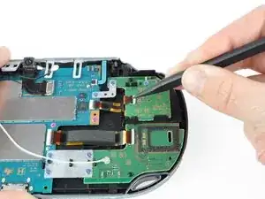
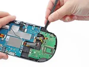
    • Using the pointy end of a spudger, pry up and release the GPS antenna cable from the motherboard.

    • Remove the GPS antenna cable.

    This part appears not to be on the PCH-1001 version, no wireless card installed.

    Aislinn -

  33. snaeBUDXAr2jcOGM
    snaeBUDXAr2jcOGM
    BYwiLSdgERrYwJNb
    • Release the camera flex cable socket by prying up on the tab with a spudger.

  34. 3tK4XdoF53TDy1hW
    3tK4XdoF53TDy1hW
    twjjcsbOQcMKS5KT
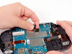
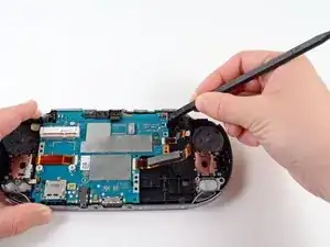
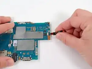
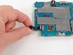
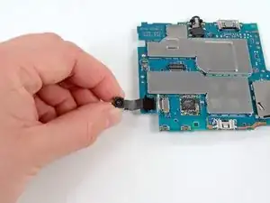
    • Using a spudger, gently pry up on the camera.

    • Work your way under the camera and along the camera flex cable, using the spudger to peel away the adhesive, freeing the camera.

  35. cAiGQxurNALpIEII
    cAiGQxurNALpIEII
    xTxZl5DyrVRqMiBT
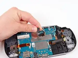
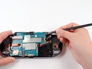
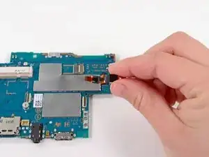
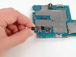
    • Carefully lift and remove the camera, sliding the flex cable out of the open connector socket.

  36. BN55rDtSYllOkUJd
    BN55rDtSYllOkUJd
    2RDZFvBsQsC5Zp3Z
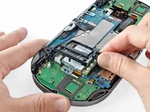
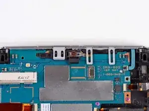
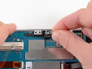
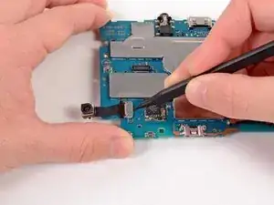
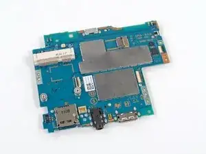
    • Using a Phillips #00 screwdriver, remove the 6.3mm screw beneath the camera.

    • Lift and remove the metal camera bracket.

  37. HGEy6JEwqIWwfrOD
    HGEy6JEwqIWwfrOD
    Jsfv1LHbxJQUCPEb
    • With the help of a spudger, lift and release the tab on the blue flex cable socket.

    Help I accidentally broke off the black tab when I was reconnecting everything and now my vita won't turn on because there is nothing holding down the blue flex cable😭😭

    Kopanoa Botsane -

    If you can't find a replacement part for either the black piece or the whole connector, try taping it down with Kapton Tape

    Nicholas -

  38. q6AxaZC3FDdPSVPT
    q6AxaZC3FDdPSVPT
    4x45J1IHVUUVeRZB
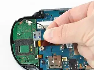
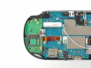
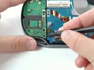
    • Using tweezers, gently pull the blue power flex cable out of the socket; rest it out of the way.

  39. FRyBB6YxjRTfUJQy
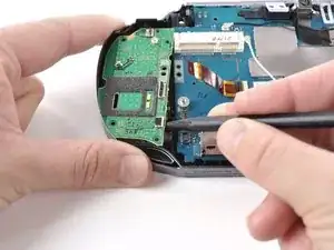
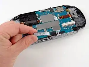
    • Using a Phillips #00 screwdriver, remove the two pink, 4.4mm screws securing the motherboard.

  40. oHMtFU314XL43Vgo
    oHMtFU314XL43Vgo
    od5JrZksLVhXwr4m
    SZD1jQKAdG2vmPB3
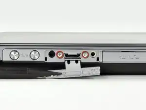
    • Gently peel the rubber tab of the game port cover off the plastic casing pins.

    • Remove the game port cover.

  41. pUiB6nI6wk3uhgJw
    pUiB6nI6wk3uhgJw
    E2QPfWCNBLdmxFvH
    fdcXliRgMoSlmNoN
    • Gently peel the rubber tab of the accessory port cover off the plastic casing pins.

    • Remove the accessory port cover.

  42. xIYUPMM2JQXi2y2n
    xIYUPMM2JQXi2y2n
    bwHfY5NADkLChbRK
    EhUHs3nMBRPOTJRO
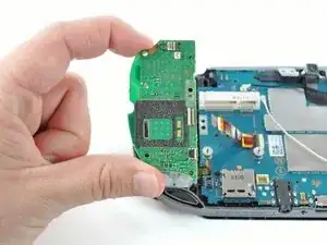
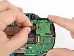
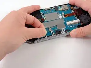
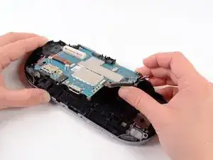
    • Starting at the upper right hand corner, use a spudger to gently lift the motherboard out of the casing assembly.

    • The motherboard is still attached to the casing by a connector on the back of the motherboard. Do not pull the motherboard all the way out, or you may damage the connector.

  43. L1xSHf6VySl4oEyP
    L1xSHf6VySl4oEyP
    YfDNDBSJnRgwdgWB
    TwbUTOPVoyRtPpYB
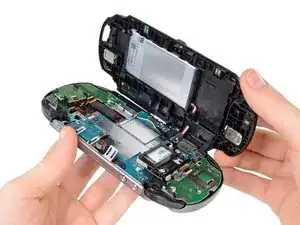
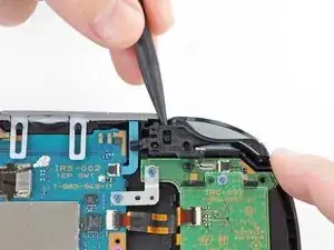
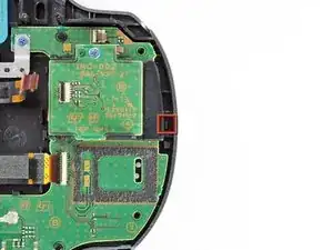
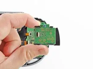
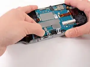
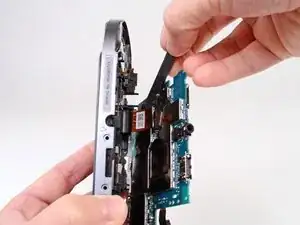
    • Lift the motherboard out and identify the OLED connector still attaching the motherboard to the casing.

    • Holding the Vita on its side, use a spudger to gently pry off the OLED connector from the motherboard.

    • Be sure to hold the motherboard while you release the connector as this will free the motherboard. If you are not holding the motherboard, it will fall.

  44. CojyErNLRwDqUGpS
    • Completely separate the motherboard from the case. Remove the case.

  45. WMmYwJawfRYBPeJT
    WMmYwJawfRYBPeJT
    iUpsGCoYUZtfuRMm
    hgLoG2Y4HVjXxkNd
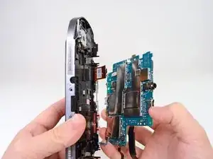
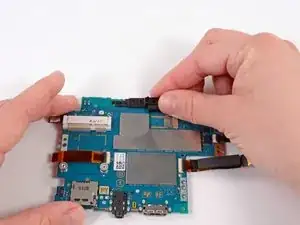
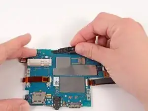
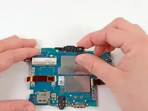
    • Starting at the right side, gently lift and remove the black casing that once held the camera.

  46. UX2YIfODfPRgrXjZ
    UX2YIfODfPRgrXjZ
    ms1G1YWQAOYyQWfc
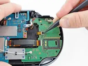
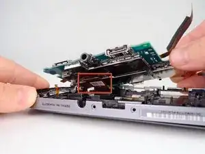
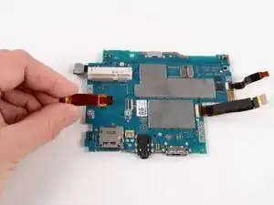
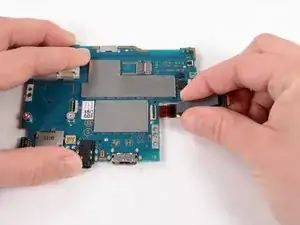
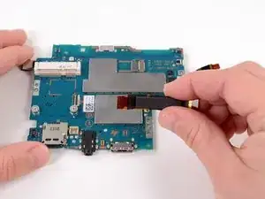
    • Using a spudger, release the tab on the ZIF connector located above the two screw posts where the wireless card once was.

  47. qVRbOVbwffd15fjs
    qVRbOVbwffd15fjs
    t2ybFNHOSWXOEabU
    1TOCJ6KwjWZrNJrZ
    • Gently pull the flex cable out of the ZIF connector, and remove it.

  48. KqTZHKQIw1PXgMPh
    KqTZHKQIw1PXgMPh
    aGHFcHyjtWuBN4Oe
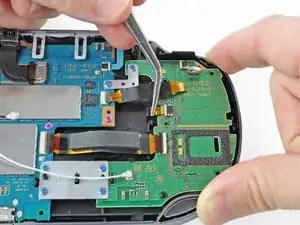
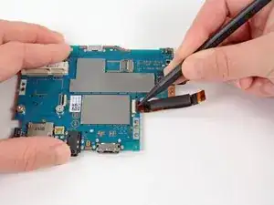
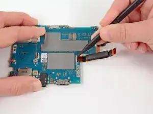
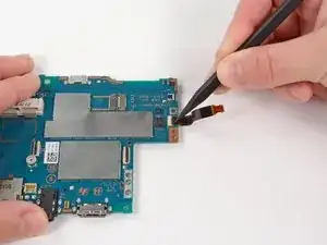
    • Release the tab on the large ZIF connector on the right side of the motherboard by lifting the tab with a spudger.

  49. KlJiWJdAwmsuoEyc
    KlJiWJdAwmsuoEyc
    vuQCJ4cE2gNMsDcq
    • Gently pull the flex cable out of the ZIF connector, and remove it.

  50. MOuvupFiAlwu53Wp
    MOuvupFiAlwu53Wp
    HfDBnjWYZ3EddQwy
    • Using a spudger, release the small ZIF connector on the right side of the motherboard.

  51. UfpIN1u4FbLsLAxK
    UfpIN1u4FbLsLAxK
    BNhjINCPGAKBbhrI
    PMZLkNU5fvk3XsnP
    • Gently pull the flex cable out of the small ZIF connector, and remove it.

  52. ukFVadeFdqstDbxM
    ukFVadeFdqstDbxM
    6QYsNMiXpSbKR1tM
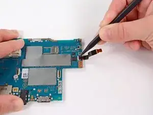
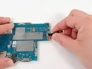
    • Flip the motherboard over.

    • With the help of a spudger, pry up and release the tab of the rear camera flex cable connector.

  53. ii3wLiNPoGP6EcTi
    ii3wLiNPoGP6EcTi
    DsW15AcgoOERvbAd
    JXOq2Qj4jaRYmnvc
    • Gently pull the rear camera out of the connector and remove it.

  54. lae3polu5dYgxLP4
    • The motherboard remains.

Conclusione

To reassemble your device, follow these instructions in reverse order.

Brittany McCrigler

Membro da: 05/03/12

88905 Reputazione

11 commenti

in steps 2&3, bottom is top and top is bottom

Samir Al Jubori -

it should be noted that the memory card should always be taken out before separating the case. I just broke my memory card slot by having a card in there while I was opening the case, there's a tiny bit of overhang that will pull the slot off the motherboard.

bryandodson -

does anyone know what firmware version the motherboard comes with?

riddochj -

These are used Motherboards. You could get a motherboards with a random FW version.

Raheem -

Okay My original Motherboard power connector broke. So nothing was wrong with it except the Power connector.

My first buy of the Motherboard screen connector broke off.

The Replacement works well, however the Touch input isn't working, unless I restore the device. After a certain amount of time it becomes unresponsive.

Do anyone have a fix before I get a 3rd replacement.

Raheem -

hello everybody, i really need help i cant manage to remove the wireless card screws. does someone has an idea how to get them out? or how to remove the mainboard without removing the screws? ( need to put it in another case)

Nico Miedreich -

these are under 3.60, right? i can buy the motherboard + tools and ship them to germany, how about customs fees?

Gianluca Daniele Di Maggio -

Can 3G boards be installed in WIFI consoles and vice-versa?

Alex Soriano -

i am replacing the whole front part of the vita meaning that im taking everything out and putting everything into a new front part of the vita because the screen wont light up, and im trying to take out the wifi chip and somehow i accidentally strip one of the 4.4mm Phillips #00 screws holding the chip down, if there is an easy (non harmful to the chip/motherboard) way please let me know !!!!!!

Saul Calderon -

This guide isnt totally correct. Some ps vita has a special screw securing the wifi module into place. I have yet to figure out what kind of screw this is. It happens to a low percentage of ps vitas but it does happen and should be noted.

Kevin Gallagher -

I recently replaced my screen but afterwards the controls always seem to be always pressing down, i cannot figure what could be causing this any help would be greatly appreciated

Simon L -