Introduzione
Changing the top case will also give you a new trackpad.
Ricambi
-
-
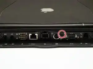
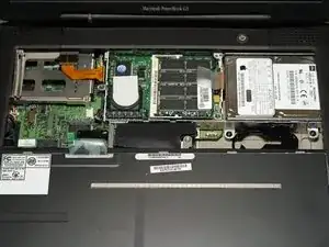
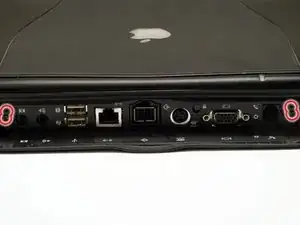
Turn the computer so that the ports are facing you.
-
If the keyboard is locked, open the port cover and turn the keyboard locking screw until the keyboard is unlocked.
-
-
-
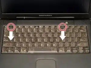
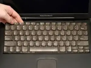
Lift the keyboard out by pulling it up and away from you. Rest the keyboard, face down, on top of the trackpad.
-
-
-
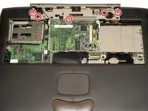
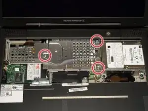
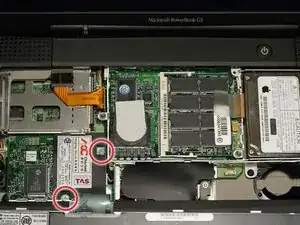
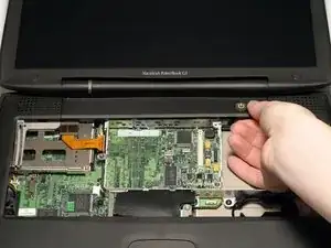
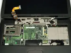
Remove the three silver Phillips screws that attach the heat shield to the internal metal framework.
-
-
-
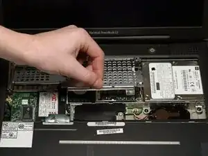
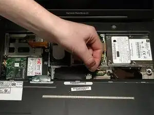
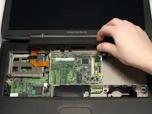
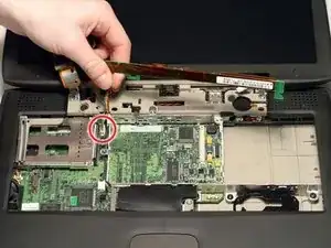
Use a spudger, the tips of your fingers, or a flat non-metal tool to get under the modem's edge and pry it up from its socket as shown in the picture.
-
-
-
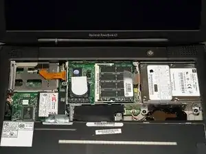
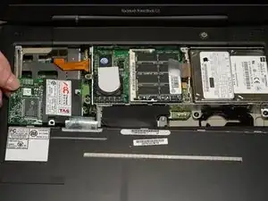
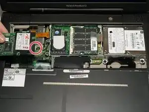
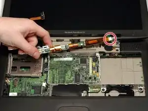
Use a spudger, the tips of your fingers, or a flat non-metal tool to pry up the processor's right side.
-
-
-
Disconnect the keyboard cable from the logic board by pulling directly up on the clear plastic loop.
-
-
-
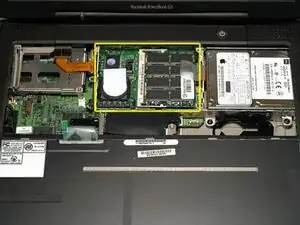
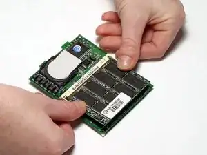
Release the tabs on each side of the RAM chip at the same time. These tabs lock the chip in place and releasing them will cause the chip to "pop" up.
-
Pull the RAM chip out.
-
-
-
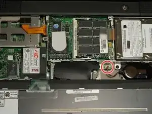
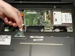
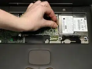
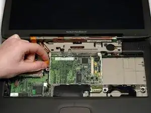
Grasp the orange cable at the left end of the hard drive and disconnect it from the logic board.
-
-
-
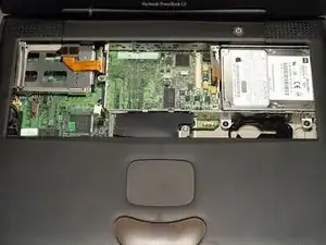
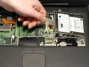
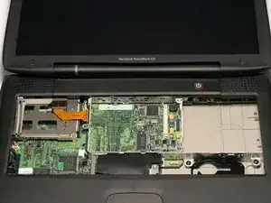
Grasp the plastic tab and pull the hard drive up and to the left, making sure that the metal bracket doesn't catch on the black plastic casing.
-
-
-
Slip a spudger or your index finger under the clutch cover near the power button and pull gently upward until you feel it come free.
-
Repeat the previous step on the left side.
-
-
-
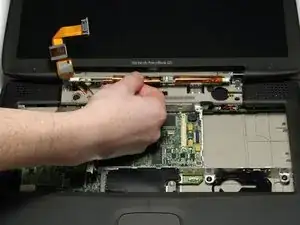
Grasp the orange display data cable and disconnect it from the logic board.
-
Pull the display cable straight up so that it is vertical.
-
-
-
Grasp the thin display inverter board at its left end, push the left end forward to get the board beyond the tab, and then lift the entire board up.
-
-
-
Turn the laptop around so that its back faces you.
-
Open the port door located at the back of the laptop.
-
Remove the four black Torx screws.
-
-
-
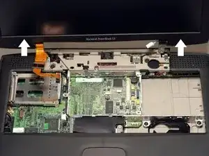
Hold the display on both sides and pull directly up until its hinges are free of their mounts.
-
-
-
Remove the three long silver and two short black Torx screws from the beige plastic casing.
-
-
-
Turn the Lombard so that the trackpad is nearest you and slide the thin plastic shield away from you, out from under the black casing.
-
Disconnect the newly revealed thin orange ribbon from the logic board, to the left of the trackpad.
-
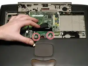
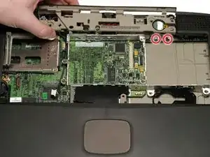
Remove the two long silver Torx screws.
-
-
-
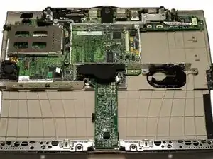
Turn the laptop back over.
-
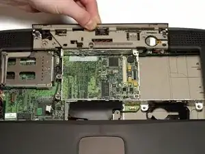
Remove the three short black Torx screws from the metal frame.
-
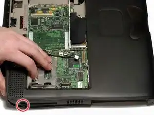
Remove the short black Torx screw to the far left that fastens the logic board to the casing.
-
-
-
Grasp the upper plastic casing where it locks into the internal frame and pull back. When the plastic tab has cleared the slot that the casing locks into, pull up enough to keep it from locking back into place.
-
-
-
The PC card eject button on the laptop's left side prevents the upper casing from lifting up. In order to bypass the button, push it in far enough so that you can pull the upper casing's left side out and up beyond the button.
-
-
-
Lift the left side of the case partly up so that you can access and disconnect the audio in/out cables from the sound card in the upper right of the case.
-
-
-
Remove the upper casing. Note that there are two tabs on the laptop's front that often cause the upper case to stick.
-


To reassemble your device, follow these instructions in reverse order.