Introduzione
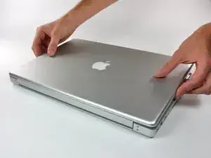
Remove your rear display bezel to gain access to your LCD and inverter. This guide requires the use of plastic opening tools and spudgers that will probably be destroyed in the process. Make sure to have a few spares of each tool handy.
Strumenti
Ricambi
-
-
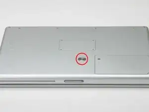
Use a coin to turn the battery locking screw 90 degrees clockwise.
-
Lift the battery out of the computer.
-
-
-
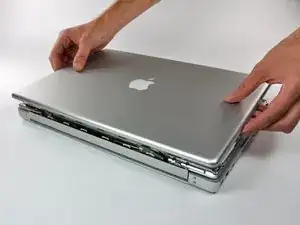
Open the computer with the display facing you and rotate the display back as far as possible.
-
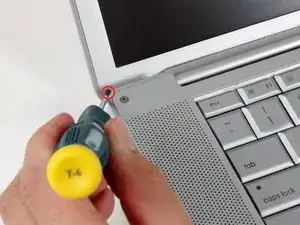
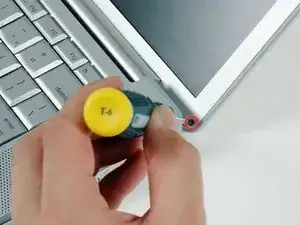
Remove the T6 Torx screw from the bottom left corner of the display assembly. The computer casing will not allow the screwdriver to be inserted directly into the screw, so be careful not to strip the screw.
-
-
-
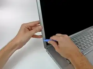
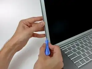
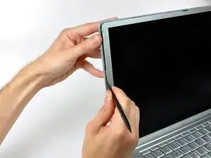
Insert a plastic opening tool between the left edge of the front display bezel and the plastic strip attached to the rear bezel, with the edge of the tool angled toward the LCD.
-
Rotate the tool away from the LCD to pop the rear bezel off the tabs on the front display bezel.
-
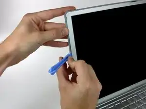
Work along the left edge of the display until the rear bezel is evenly separated from the front bezel.
-
-
-
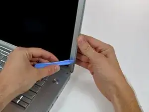
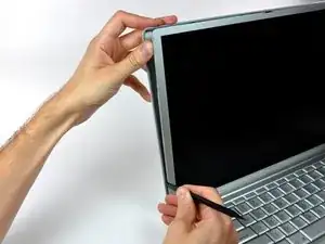
Insert a plastic opening tool between the right edge of the front display bezel and the plastic strip attached to the rear bezel, with the edge of the tool angled toward the LCD.
-
Rotate the tool away from the LCD to pop the rear bezel off the tabs on the front display bezel.
-
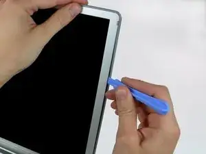
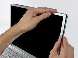
Work along the right edge of the display until the rear bezel is evenly separated from the front bezel.
-
-
-
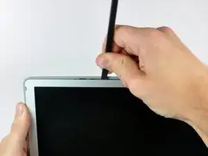
Insert a spudger just to the left of the hinge opening on the top edge of the display between the front display bezel and the plastic strip attached to the rear bezel.
-
Pry the rear bezel away from the front bezel along the top left half of the display.
-
-
-
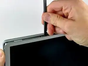
Insert a spudger just to the right of the hinge opening on the top edge of the display between the front display bezel and the plastic strip attached to the rear bezel.
-
Pry the rear bezel away from the front bezel along the top right half of the display.
-
-
-
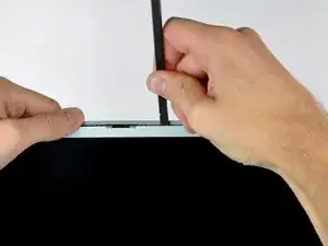
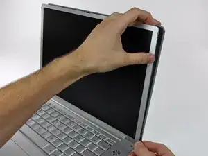
Now that the top edge is released, use a spudger to completely release the clips along the left edge of the display.
-
-
-
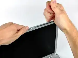
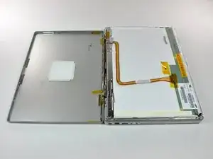
Close the display.
-
Rotate the top edge of the rear display bezel slightly away from the rest of the display, and then lift the lower edge of the rear bezel away from the clutch cover.
-
-
-
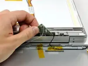
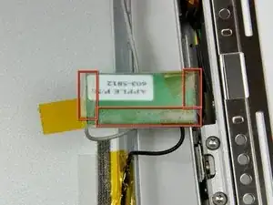
Carefully lift the antenna board out of the clutch assembly.
-
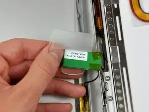
Peel the three self-adhesive flaps off the plastic cover on the underside of the antenna board.
-
Remove the protective plastic cover from the antenna board.
-
-
-
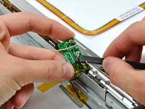
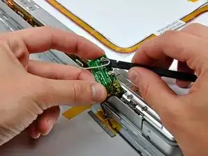
Use the flat end of a spudger to disconnect both antenna connectors from the antenna board.
-
The rear bezel can now be completely removed from the LCD assembly.
-

To reassemble your device, follow these instructions in reverse order.