Introduzione

Use this guide to replace the trigger on your Razer Kishi.


Both controller sides of the Razer Kishi are almost identical in construction. The process of replacing the triggers are almost identical on both sides, so in this guide we only show the right side.

  1. ZsQTaZjqv6qyxclm
    • The opening process is the same on both sides. For simplicity, this guide shows only the right-side opening process. Unscrew whichever side you wish to open and work on.

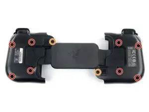
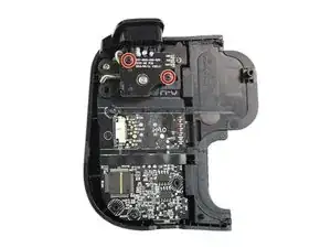
    • For the right side, remove the five Y0 screws securing the right side of the controller.

    • Four 9.2 mm screws

    • One 7.2 mm screw

    • If you wish to open the left side, remove the five Y0 screws securing the left side of the controller.

    • Four 9.2 mm screws

    • One 7.2 mm screw

  2. GBYT3l1JQI1klrJF
    GBYT3l1JQI1klrJF
    ABTZOrHBxBJQODSx
    5tBZLnQyNfh5Ryad
    • Both cases are held together by plastic clips.

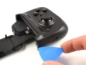
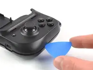
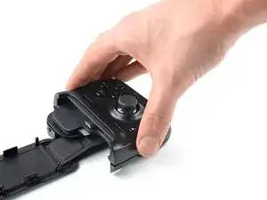
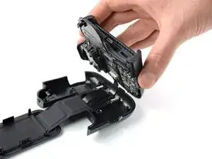
    • Insert an opening pick in the seam between the top and bottom case, at the bottom left corner of the controller.

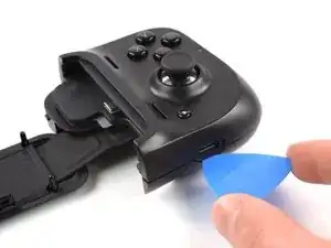
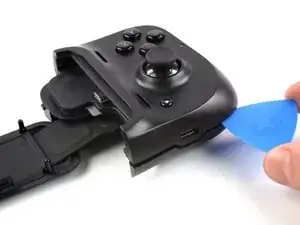
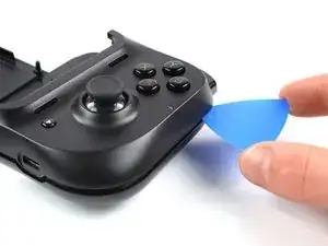
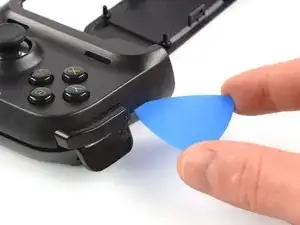
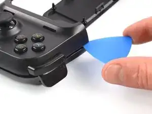
    • With the pick still in the seam, slide it along the bottom edge to the bottom right corner to loosen the plastic clips.

  3. 4eVLGWoQLpMt5mOy
    4eVLGWoQLpMt5mOy
    ChPKLarayLVEACmg
    • Slide the opening pick along the right edge to loosen the plastic clips.

  4. lLInivpTrkn6Q6Q6
    lLInivpTrkn6Q6Q6
    266AxEQXlBUIHFcU
    • Slide the opening pick along the top edge to loosen the remaining plastic clips.

    • Don't try to remove the top side yet, the case is still connected to the board.

  5. DpyMIvfffLhtnj6j
    DpyMIvfffLhtnj6j
    lPis15eO3pD5JKUh
    PlswYISvGHE1BtJ3
    • Carefully lift the top side and unfold it to the right, like a book.

  6. gPHMigOchnXaqynE
    gPHMigOchnXaqynE
    vWZ5QoSsBGMIacE5
    KvZaXgvL5W3Bjs4m
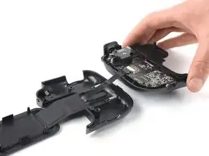
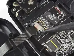
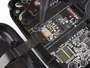
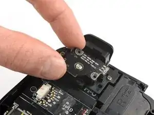
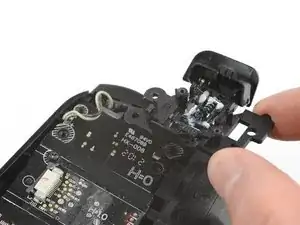
    • Using the pointed end of a spudger, push the grey tabs on the interconnect socket away from the socket, parallel to the interconnect cable, to release the cable.

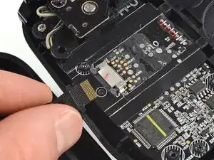
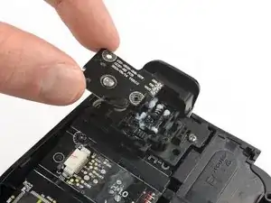
    • Pull the cable out of the socket.

  7. Z6Y3RS5pjXnYPLlS
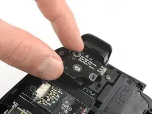
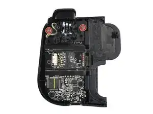
    • Use a Phillips #0 screwdriver to remove the two 4.4 mm-long screws securing the trigger board.

    Phillips #00 on mine.
    Model no. RZ06-0290

    also listed: GV190

    Stephen Marshall -

    This step is not essential and risks misaligning the rotary knobs from their tracks as well as losing or contaminating the lubricant. You can leave the breakout board attached to the trigger and remove them together. When the trigger screws are out, lift the whole assembly together, being very careful to lift it straight out to avoid bending the jumper pins.

    Stephen Marshall -

  8. nyCJQtxgXe1abwUu
    nyCJQtxgXe1abwUu
    iBH5uaM25xQHkDJ1
    vAlYNZgnwsE6ffis
    • The breakout board is plugged in. When removing breakout board, it is important to pull it straight out to avoid bending the connectors.

    • Remove the breakout board by lifting it straight up, away from the controller.

    When reassembling this piece, ensure that the breakout board's rotating peg is aligned with the neutral position of the joystick. To do this on the left trigger:
    1. Flip the breakout board over so that the rotating peg is facing you and position it such that the 3 jumper pins are in the top right (and the text is right-side-up.

    2. Carefully rotate the peg until it faces North-East, at just about a 45 degree angle from the horizontal. Move it in whatever direction requires the shortest travel to arrive at this point. Be wary of the lubricant which coats this part and try not to remove much.

    On the right trigger, this process is the same but mirrored. Align with pins in top left and point peg to the North-West at 45 degrees.

    Stephen Marshall -

  9. QJtOBeEycsUgh1XX
    • Use a Phillips #0 screwdriver to remove the two 7.0 mm-long screws securing the trigger.

    These are #00 screws on mine

    JM Palacios -

    These screws have a very shallow angle for the inner Phillips drive, making them feel very easy to strip. For these, a Phillips #1 actually provided the most positive fit. Test a few tips just to be sure.

    Stephen Marshall -

  10. XUOOHSJRrtCoPIIv
    XUOOHSJRrtCoPIIv
    HPAqiPYkiZ1VBygg
    • Remove the shoulder trigger.

Conclusione

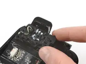
To reassemble your device, follow these instructions in reverse order.

Take your e-waste to an R2 or e-Stewards certified recycler.

Repair didn’t go as planned? Try some basic troubleshooting, or ask our Answers community for help.

Adriana Zwink

Membro da: 18/12/19

47656 Reputazione

5 commenti

Thankyou so much my trigger slipped out and this was extremely helpfull ??

Julian Nicholes -

Hola donde puedo conseguir las partes de repuesto?

WALTER GUERRA -

THANK YOU VERY MUCH! My R2 trigger got removed and its hinge is cracked, just super glued it but I have no idea how to fix it. Thanks to this guide, I returned it easy with no damages. (Took 15 minutes on a newbie like me)

RaceRider102 -

Excelente.... ¡ Y donde consigo el repuesto?

WALTER GUERRA -

During reassembly, when snapping the outer shell together test the R2 button. If it won't move it's likely because the tab on the end got pushed to the outside of the case. Pop it back open and push the R2 button in as you snap it back together in that area.

JM Palacios -