Introduzione
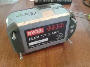
Questa guida è specifica per la batteria agli ioni di litio
da 18 V del Ryobi One+ (130501002), ma può essere usata più in generale. Questa guida ti mostrerà come smontare il gruppo della batteria, controllare il bilanciamento delle celle e come ribilanciarla se necessario.
La batteria dovrebbe misurare 18 V tra i suoi contatti (massimo 21 V). Se misuri 12 V, è probabile che si sia attivato il circuito di protezione della batteria a causa dello sbilanciamento delle celle (o almeno questi erano i sintomi nel mio caso).
Ribilanciare le celle può aiutare anche se la batteria non si carica più completamente (l'indicatore del livello di carica non si illumina di verde).
Il tempo stimato per questa guida è per lo smontaggio e la misura del bilanciamento delle celle. Il ribilanciamento necessita del tempo in più.
ATTENZIONE: Smontare la batteria espone i circuiti a corrente elevata. Stai attento!
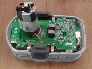
La batteria è in una configurazione 2P5S (un gruppo di 2 celle messe in parallelo, e 5 gruppi in serie). Usa delle celle agli ioni di litio Sanyo 18650.
-
-
ATTENZIONE: Smontare la batteria espone i circuiti a corrente elevata. Stai attento!
-
Svita le quattro viti Security Torx T15 dalla base.
-
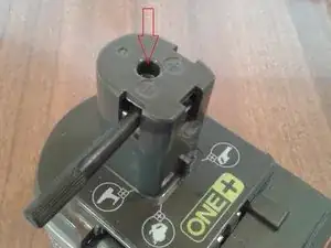
Svita una vite Torx T10 dalla parte superiore.
-
-
-
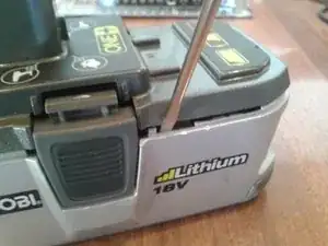
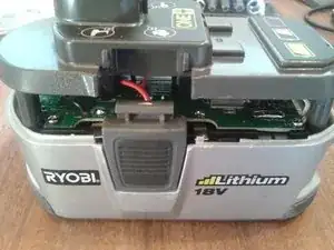
Fai leva sui ganci della copertura per rimuovere quella superiore.
-
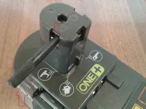
Usando uno strumento non conduttivo, fai leva sul gruppo dei contatti della batteria infilandolo nella copertura superiore.
-
ATTENZIONE: usando uno strumento in metallo per il passaggio precedente rischi di far fare corto circuito ai contatti della batteria.
-
-
-
Una volta creato uno spazio sufficiente, tieni fermo il gruppo dei contatti della batteria mentre sfili la copertura superiore.
-
I ganci di bloccaggio della batteria sui lati possono essere rimossi se vuoi.
-
-
-
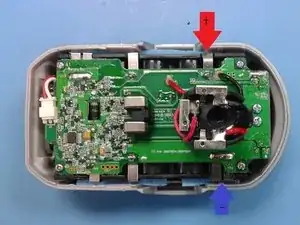
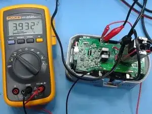
Con un multimetro digitale (voltmetro) impostato in modalità tensione DC, Misura il bilanciamento delle celle. Le strisce in nichel sono un buon punto di misurazione. Segnati la tensione delle celle.
-
Cella 1 : da TP6 a CL1.
-
Cella 2: da CL1 a CL2.
-
Cella 3: da CL2 a CL3.
-
Cella 4: da CL3 a CL4.
-
Cella 5: da CL4 a CL5 (polo positivo).
-
La tensione delle celle dovrebbe essere tra gli 0,3 V e i 4,2 V. Se tra le celle c'è una differenza di più di 0,1 V, lo sbilanciamento delle celle può essere un problema per il tuo gruppo della batteria.
-
-
-
Usa un alimentatore da banco con tensione e limite della corrente impostabili. Servono anche un misuratore di tensione e uno di corrente. Ad esempio un Topward serie 3000. Imposta la tensione pari a quella più alta che hai misurato sulle celle, ma non più di 4,2 V. Imposta la tensione a 0,5 A.
-
Collega l'alimentatore alle per ricaricarle (ribilanciarle), positivo con positivo e negativo con negativo. Abbiamo usato dei cavi a coccodrillo per questo passaggio.
-
Mentre la cella si carica la tensione salirà e si fermerà una volta raggiunta quella impostata, quindi la corrente inizierà a scendere verso zero. Quando la corrente arriverà quasi a zero, la cella sarà caricata.
-
Scollega l'alimentatore dalla cella e rimisurane la tensione.
-
Ripeti la procedura di carica per le altre celle finché sono tutte entro 0,1 V l'una dall'altra.
-
Per rimontare il dispositivo, segui le istruzioni in ordine inverso.
56 commenti
Using this guide, I successfully dismantled my 18V Ryobi Li-Ion battery with no problem. THANKS edwardb! In my case, I do have cell voltage imbalance exceeding 0.1V (3.48 to 3.36V). I would like to get your feedback on an alternate STEP 5 since I don't have a variable power supply yet. It seems that we recharging the individual pairs of SANYO cells to the same voltage so that the protection circuit will function properly again and allow the reassembled Ryobi battery to be recharged again using the standard Ryobi chargers. If this is this correct, then there might be 2 other options for reducing the cell imbalance to less than 0.1V as mentioned in STEP 5.
OPTION 1: Carefully deplete the cells having the higher voltage to reduce the voltage imbalance to less than 0.1V, or
OPTION 2: Carefully charge the lower voltage cells using a solar panel that has a power rating of less than 4.2Vx0.5amps =2 watts.
Would either OPTION 1 or 2 work?
Hi Al, Glad the guide is useful.
Yes your option 1 or option 2 would both work.
For option 1, use a power resistor with sufficient rating (say 10 ohm, 2W). Careful monitoring would be needed. Be sure to stay above 3.0V.
Option 2 should work fine too, might take a while depending on how many cells you can charge while the sun is out (and giving you good power in the solar panel).
Good luck
Ed
edwardb -
Ed, thanks for your quick response. This is how I re-balanced my cells. I charged the 4 lowest voltage cell pairs, one at a time, to the same level as the highest voltage cell (3.48V) using a spare 18V Ryobi battery. I connected one cell tab to one terminal of the spare Ryobi using thin bell wire (it's like speaker wire). The polarity is critical (negative-to-negative, or positive-to-positive). I then attached one end of another bell wire to the other terminal of the spare Ryobi. With the free end, I made frequent intermittent contact with the other cell tab. This means touching the wire to the cell tab long enough to see sparks and repeat the contact every 5-10 seconds, depending on how fast the wire heats up. If the wire is hot, then increase the interval between sparking. During this procedure, it is important to monitor the voltage across the cell. In less than a half hour, all cells were charged. After reassembly, I was able to charge the battery up to about 19.8V, a bit less than usual (20.5V). Amazing!
How about another alternative: why not use one of the higher voltage cells to charge one of the lower voltage cells? Put two of the cells together with a resistor or series of resistors in between them.
If my EE skills are in tact, you could put a chain of 470 milliOhm 1/4W resistors in series - one for every .1V difference. As the voltage difference drops, remove a resistor from the chain until there is only 1 resistor between the two cells that differ by .1V.
So for example, if one cell was 4.2 V and another was 3.6 V, put 6 of the resistors in series. When they go to 4.2 and 3.7 remove a resistor, when they go to 4.1 and 3.7 remove a resistor until one is 3.9 and the other is 3.8.
Mouser sells these resistors for less than 20 cents here: http://www.mouser.com/ProductDetail/Yage...
Your thoughts?
Kenton -
Kenton, you need to consider your application from the energy perspective. Cells in a Ryobi battery are normally cycled from 3.5 to 4.1V, resulting in 4.8 Wh output/cell. In your example, the 4.1V cell would lose about 1Wh of energy while discharging to 3.9V, based on what I’ve read on the internet. That energy would be distributed to a) the charging of the weaker cell, b) the heat load of your resistors, and c) the charging inefficiencies. For item a), the weaker cell would need about 2Wh charging from 3.6 to 3.8V. For item b), the resistors would dissipate <0.1Wh in one hour at say 0.3 amps. For item c), I would not be surprised if it takes an extra Wh to charge an cell by 2Wh. At the end of the day, you would likely have 2 depleted cells.
Ed’s original intent was to rebalance the cells without removing them from the Ryobi battery. For your approach, you would need to remove the cells if both the stronger and weaker cells come from the same battery pack. Hope this helps. What do you think Ed?