Introduzione
Before you start
This process involves replacing electrical components. Ensure the drill is completely disconnected from any power source!
It is very important to ensure the electrical connection are correctly replaced so the drill works properly upon reinstallation.
If a cellphone with a camera is accessible to you, it may help to take more close-up pictures of the drill before disassembly.
This process requires very little tools, pliers may be helpful but are not required. all of the electrical connections on the trigger are push connections. Some connections are tougher to remove than others so you might need to pull harder than you think.
Ricambi
-
-
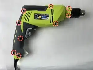
All nine 16mm long Torx20 screws (Circled in red).
-
Turn the screwdriver counterclockwise to loosen the screws.
-
Remove all nine screws completely.
-
-
-
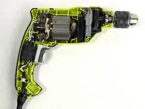
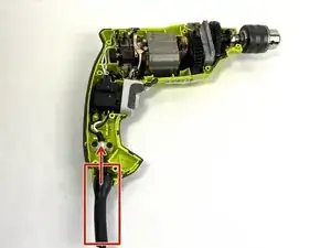
Follow the wires coming out of the bend relief cover to the white power cord clamp with the two 14 mm black PH1 screws.
-
-
-
Unscrew the two 14 mm PH1 screws holding the power cord wire in place.
-
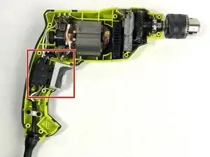
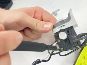
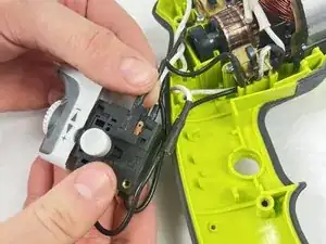
Lift the switch box from its place gently.
-
-
-
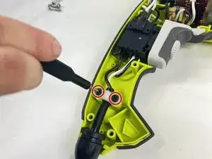
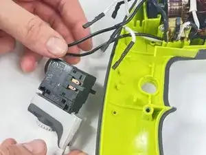
Remove the two little screws holding the brass terminal lugs in place. Although it is not required, you can remove the screws completely if you find that doing so is more convenient.
-
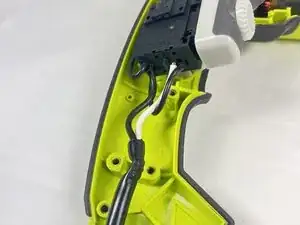
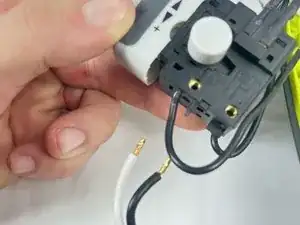
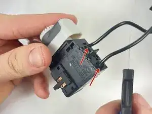
Gently pull the white positive and black negative wires that are connected to the switch box.
-
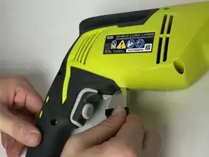
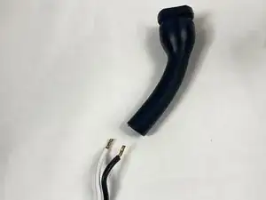
Slide the bend relief guard off the cord towards the loose connections.
-
To reassemble your device, follow these instructions in reverse order.