Introduzione

Use this guide to remove or replace the Note's USB board/daughterboard

  1. kG2UScBcTXmHPYVN
    kG2UScBcTXmHPYVN
    r4XSpAUaXIPiQtya
    • Grasp the cap of the stylus and remove it from its slot in the midframe.

  2. PI2tDAugVYFNGMZt
    PI2tDAugVYFNGMZt
    ULINckCfSInHyeXC
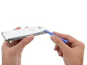
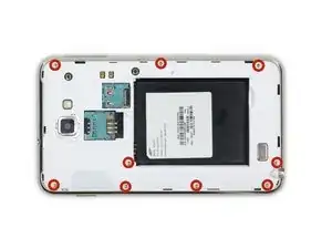
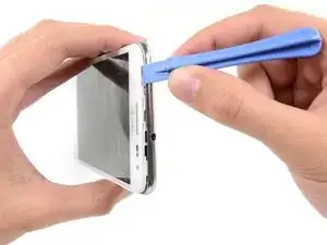
    • Pry with a plastic opening tool, or your fingernail, in the divot to the right of the rear-facing camera, near the volume rocker.

  3. MpHKKCVKwRo1RioU
    MpHKKCVKwRo1RioU
    LjfTJSNt4T2cjv6h
    • Lift and remove the rear case from the phone.

  4. SWy2hhjKDS33U3Y3
    SWy2hhjKDS33U3Y3
    GGlu32H1KPjCmsW6
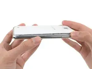
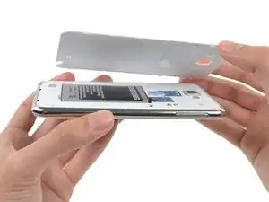
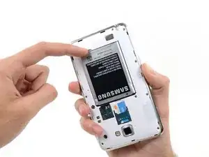
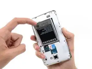
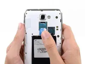
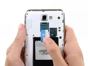
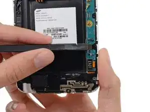
    • Insert your finger in the notch of the battery compartment.

    • Press the battery toward the rear facing camera while pulling outward.

  5. 5BiCRBrtTPyJ4tk1
    5BiCRBrtTPyJ4tk1
    UFTfVPJSKVrPKL5Y
    EJuYT2OyjoQGAbxv
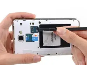
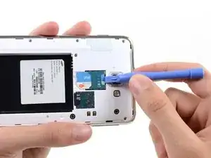
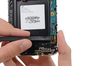
    • Use the flat end of a spudger, or your fingernail, to press the microSD card slightly deeper into its slot until you hear a click.

    • After the click, release the card and it will pop out of its slot.

    • For reassembly, push the microSD card into the slot until it clicks in place.

  6. 52J2RI4TEZeQ11sJ
    • Remove the microSD card from its slot in the midframe.

  7. d4aAiV1JVukpJiKw
    d4aAiV1JVukpJiKw
    eqYi4EUXGynt1yET
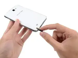
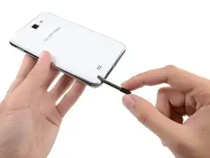
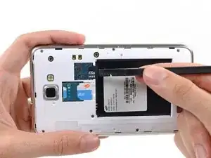
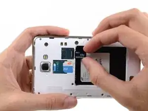
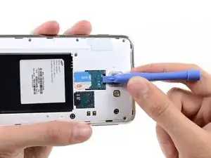
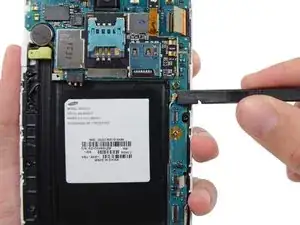
    • Use a plastic opening tool, or your fingernail, to push the SIM card out of its compartment.

  8. YRSAICOyCpBuNyUE
    YRSAICOyCpBuNyUE
    1OHC6HOFbMFrhtpE
    • Slide the SIM card out the rest of the way with your thumb and remove it from the device.

    My sim in not working in this phone what should I do

    soha Javed -

  9. hNi5V3SbxPG1DZ1M
    • Remove the nine 3.4 mm Phillips #00 screws securing the midframe to the display assembly.

  10. rFPT6b3gYdjYmtS1
    rFPT6b3gYdjYmtS1
    BGPTnIyIZGYetEFv
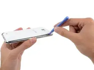
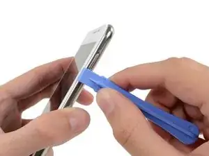
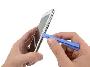
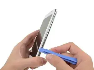
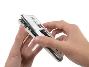
    • Insert your plastic opening tool to the left of the power button between the midframe and the front panel assembly and pry.

  11. VYiMNujtYmq4HTwa
    VYiMNujtYmq4HTwa
    Da1wnT3vJkTHsRdX
    PEMbIiI53Gg4VTUN
    • Slide the plastic opening tool down the seam.

  12. JdiLLBSNwDBK2cSw
    JdiLLBSNwDBK2cSw
    qLogubShioBGLvqh
    JTIw65fNcodstZe6
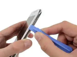
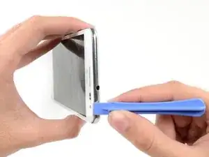
    • Insert your plastic opening tool to the left of the headphone jack between the midframe and the display assembly.

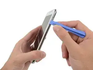
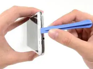
    • Slide the opening tool along the top edge of the phone.

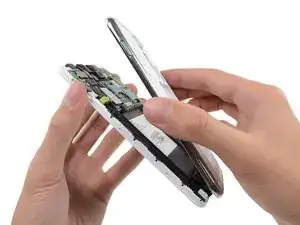
    • Continue to run the plastic opening tool around the perimeter of the phone until the midframe is separated.

  13. PHSBcEoqFQgTMAVK
    PHSBcEoqFQgTMAVK
    4amJJFHaMvBcf13p
    • Remove the midframe from the display assembly.

  14. kosVNS1uAGPxAZAG
    kosVNS1uAGPxAZAG
    bLuU4EJIB16wP1hI
    • Use the flat end of a spudger to carefully disconnect the display cable connector.

  15. 1bFpbsFaVkKtXTpX
    1bFpbsFaVkKtXTpX
    GRsOCuglVJykACAS
    YfiK2H5wU1eNNJgA
    • Use a spudger to disconnect the front-facing camera assembly cable connector.

    • Disconnect the headphone jack/earpiece speaker assembly cable connector.

    • Disconnect the digitizer cable connector.

  16. N2UAEgSjgjErB2Qc
    N2UAEgSjgjErB2Qc
    EbBQebZEVKgPmw41
    ZnvokTfp5QYpjY2t
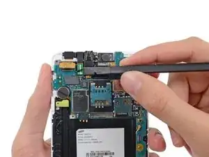
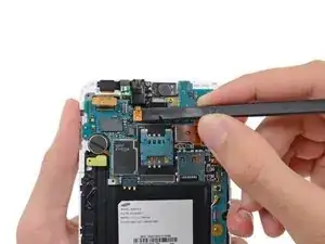
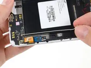
    • Disconnect the soft button cable connector with the flat end of a spudger.

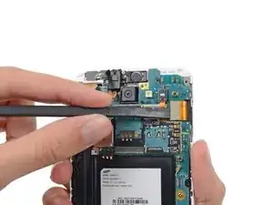
    • Use a spudger to disconnect the USB board cable connector.

    • Disconnect the antenna cable connector.

  17. cBghSlKcHnCMGBZr
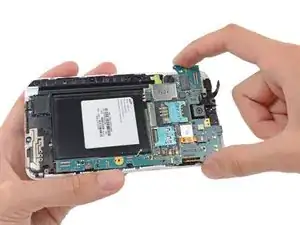
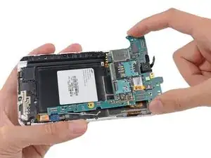
    • Remove the two 3.4 mm Phillips #00 screws securing the motherboard to the display assembly.

  18. uphlJRIiwtJI6Dxt
    uphlJRIiwtJI6Dxt
    1GqrPWFQjZMMQdKM
    • Remove the motherboard assembly from the display assembly.

  19. YphhDLbRUgqTiZoR
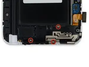
    • Remove the three 3 mm Phillips #00 screws securing the speaker enclosure to the front panel assembly.

  20. X24CdbE3l14FMYSV
    • Lift the speaker enclosure from the display assembly.

  21. csw5yerKyQVVemMK
    csw5yerKyQVVemMK
    Fi5XWxahGYRgEOsN
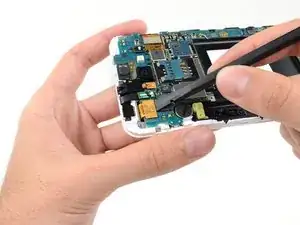
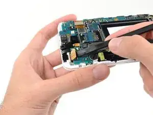
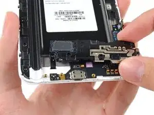
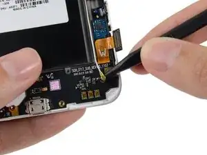
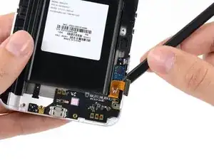
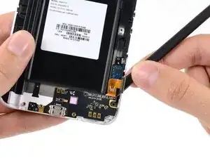
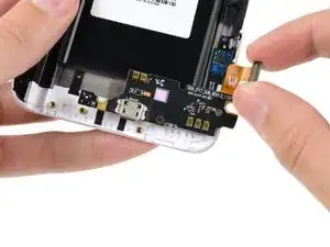
    • Use the tip of a spudger to disconnect the antenna cable connector from the USB board.

    • Remove the antenna cable.

  22. VvhdqNFAa4GSpYwr
    VvhdqNFAa4GSpYwr
    G2XUMkTN6fEGZPdT
    jCPoXAPJoPlOQdLt
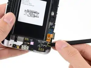
    • Push the flat end of a spudger under the USB board to separate it from the display assembly.

    • Insert the spudger at a shallow angle to avoid bending or damaging the USB board.

  23. MJoGiedURnnXBDcU
    • Remove the USB board.

Conclusione

To reassemble your device, follow these instructions in reverse order.

Sam Goldheart

Membro da: 19/10/12

465140 Reputazione

6 commenti

Using the Guides on online and the PDF guides made this repair easy and quick!

Joe -

It's not necessary to remove the motherboard (steps 17 and 18) to complete this repair. The flat flex running to the USB board can be easily slid out from under the motherboard with the motherboard still in position. Just omit steps 17 and 18 and the rest of the procedure works fine. I've done it twice.

Phil -

Where in England could I buy the USB Board part?

Craig Pyle -

USB board bought off ebay. Didnt need plastic opening tools, thumb nail worked easier than expected.

john dingley -

It's not the Galaxy Note GT-N7000!

costantino -

Make sure to match the rev on the board! Now I can finally enjoy using the phone while plugged in again.

John Cobra -